Figure: The Aspect Process Pipeline and its components. Original PostScript figure (72kB).
Next: Fitting and Modeling in the ASC Data Analysis Environment
Previous: Modeling AXAF Obstructions with the Generalized Aperture Program.
Up: AXAF
Table of Contents - Index - PS reprint
M. Karovska, T. Aldcroft, R. A. Cameron, and J. DePonte
Harvard-Smithsonian Center for Astrophysics,
Cambridge, MA 02138, USA, E-mail: karovska@cfa.harvard.edu
M. Birkinshaw
Department of Physics, University of Bristol, Bristol, BS8 1TL, UK,
and
Harvard-Smithsonian Center for Astrophysics,
Cambridge, MA 02138, USA
The aspect determination system (ADS) is responsible for the collection of data that allow the pointing direction and roll angle of the AXAF Observatory to be reconstructed from the telemetry. The major parts of this subsystem are:
The AXAF aspect camera is a 0.11m diameter Ritchey-Chrétien telescope with a 3-element refractive corrector, which images about 2 square degrees of sky into one of two red-sensitive 1024×1024 CCDs. The optics of the camera are deliberately defocused, so that the FWHM of star image is about 9´´, well spread out relative to the CCD scale of 5´´/pixel. The aspect camera directly views the optical sky, and also views fiducial lights arranged around an X-ray detector, imaged via the fiducial transfer system consisting of a retroreflector/collimator and periscope (see Birkinshaw & Karovska 1995). Up to eight images (normally five guide stars and three fiducial lights) are tracked by the aspect camera, and their astrometry provides a history of the celestial pointing coordinates and roll angle for each X-ray observation.
The Ground Aspect Determination System (GADS) pipeline is a collection of tools which process aspect telemetry and generate aspect data products. It produces a three-axis aspect solution in J2000.0 celestial coordinates, to support both image reconstruction (with error less than 0.5´´) and celestial location for X-ray data (with error less than 1´´).
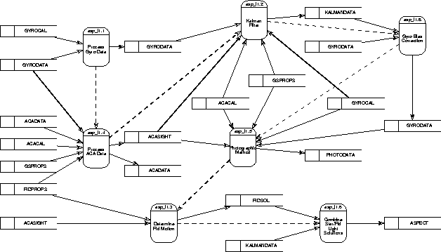
Figure: The Aspect Process Pipeline and its components.
Original PostScript figure (72kB).
The aspect solution is calculated from telemetry data (ACADATA and GYRODATA on Figure 1), generated by the aspect camera assembly and the inertial reference units (gyroscopes), using their associated calibration and alignment data (GYROCAL, ACACAL, GSPROPS, and FIDPROPS in Figure 1). The ACA telemetry contains pixelated images of stars between 10th and 6th magnitude and fiducial lights, nominally at 7th magnitude apparent brightness, at intervals of 1.025, 2.050, or 4.100s (corresponding respectively to 4×4, 6×6, and 8×8 pixel images). The AXAF IRUs provide four axes of integrated angular rate telemetry at 0.25625s intervals, from which three orthogonal axis rate data are derived.
The aspect camera data are analyzed to determine the centroid of each star or fiducial light image. The star centroids are combined with the IRU rate data in a Kalman filter to provide a time-varying optimal aspect solution and associated covariance matrix, assuming known noise models for the aspect camera and IRU data. The relative offsets between the star centroids and the fiducial light centroids are then calculated. Finally, the boresight calibration is applied to the relative offset, to transform the optical celestial aspect solution to the X-ray focal plane data. The GADS pipeline also performs a simple least-squares simultaneous fit of ACA position data and IRU rate data, and generates ``photographs'' of the ACA guide stars, for diagnostic and simple quality-assurance purposes. The pipeline also determines intervals during which the aspect solution is stable, assigns aspect quality indicators, and updates databases and the AXAF Optical Star Selection (AOSS) catalog.
The aspect pipeline consists of three components:
The Aspect Process Pipeline (Figure 1) is the central part of the aspect determination pipeline. The functional components of this pipeline are:
We plan to use a PSF-fitting routine to calculate centroids and
fluxes for each star and fiducial light image, where the PSFs
obtained by interpolating from a database of theoretical PSFs
of the optical system. Each model PSF is defined on a pixel
grid that is finer than that of the aspect camera itself, and is
calculated using the parameters of the optical system as
measured before launch or on orbit.
Using a subset of ACA pixel data from the Aspect Interval, we
identify poorly-fitting PSFs and find spoiler stars in star and fiducial
light images. (Spoilers are faint stars in the vicinity of guide
stars or fiducial lights). We then create new ``effective'' PSFs
incorporating any spoilers, for image
centroiding. We apply multidimensional  minimization routines
(e.g., Powell
minimization routine) to derive the optimal values for the
coordinates and brightness of the image and the local sky background
level.
minimization routines
(e.g., Powell
minimization routine) to derive the optimal values for the
coordinates and brightness of the image and the local sky background
level.
AXAF Science Center and SAO staff that contributed to this work include: Daniel Schwartz, Martin Elvis, Jonathan McDowell, Gerald Cardillo, and Peter Daigneau. We thank Nanci Kascak from TRW for providing us with the Kalman filter and gyro model code. This work was supported by NASA Contract No. NAS8-39073.
Birkinshaw, M., & Karovska, M. 1995, AXAF News, No. 3
Next: Fitting and Modeling in the ASC Data Analysis Environment
Previous: Modeling AXAF Obstructions with the Generalized Aperture Program.
Up: AXAF
Table of Contents - Index - PS reprint