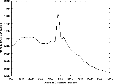
Figure 3: Averaged transverse intensity profile across the
entire jet at 8.4 GHz with 1.3" (FWHM) resolution.
|
The total intensity profiles shown in Figures 2 and 3 illustrate that there is also excess emission within three to five jet radii (4 to 8/h kpc) of the jet axis. This excess, or ``sheath'', is not simply a broad band around the jet that is fully filled with diffuse emission. As well as some diffuse emission, it contains bright ridges resembling the lobe filaments, and a relative absence of emission close to the jet.
|
The transverse-integrated intensity of the sheath tends to increase
with that of the jet (Figure 4). The sheath is first detected at
about the same distance from the nucleus as the first jet knot, but
brightens less abruptly than the jet. Its ridge-like substructure
complicates quantifying its collimation, or how well it aligns with
the jet; but integrating transverse profiles of total and polarized
intensity along axes at 0°, ±10° and
±20° to the jet implies that sheath and jet are coaxial
to  10°. We cannot exclude the possibility that the
sheath is merely part of the filamentary structure
of the lobe that is superposed on the jet
by chance. The connection between their intensities (Figure 4)
suggests, however, that the sheath includes features that influence,
or are influenced by, the passage of the jet. There is no evidence of
a similar sheath around the counterjet.