Next: Modeling AXAF Obstructions with the Generalized Aperture Program.
Previous: Simulated AXAF Observations with MARX
Up: AXAF
Table of Contents - Index - PS reprint
Astronomical Data Analysis Software and Systems VI
ASP Conference Series, Vol. 125, 1997
Editors: Gareth Hunt and H. E. Payne
R. A. Zacher, A. H. MacKay, B. R. McNamara, and L. P. David
SAO/ASC, Cambridge, MA 02138
Abstract:
We are developing and integrating software to simulate the focal
plane detectors, shutters, and gratings for the Advanced X-ray
Astrophysical Facility (AXAF). AXAF is one of four observatories in
the NASA ``Great Observatory'' series,
scheduled for launch in 1998. AXAF will offer
unprecedented spatial and spectral resolution in the X-ray
band ranging from 0.1-10keV. The path of X-ray
photons is simulated from the exit of the telescope mirrors to the
focal plane. Each major functional element of the simulation is
represented by an independent module. Module execution and
inter-module communication is accomplished within a
pipeline architecture. The software is written in C/UNIX and
utilizes a number of existing astronomical software libraries.
Detailed models are being developed for the two focal plane
instruments. These instruments are ACIS, which is a CCD
camera, and HRC, which is a microchannel plate detector.
Realistic detector output files are generated in a variety of
formats. The simulations are currently being used for planning
calibration activities, on-orbit
performance prediction and for testing the analysis and telemetry
software.
We are developing computer models to simulate the focal
plane detectors of the Advanced X-ray Astrophysical
Facility (AXAF). The models, being developed as part of the AXAF
Science Center, are being used to aid in calibration
planning and to characterize the performance of the AXAF
observatory. Scripts have been developed to configure and
run the simulations automatically from a test database.
Depending on the output mode selected, the results can be
viewed directly, sent through telemetry processing, or fed
into higher-level analysis pipelines in the Data System.
Much of our work has been focused on developing high-fidelity
simulations of the two main Scientific Instruments located in the
focal plane of the telescope. These are the AXAF CCD Imaging
Spectrometer (ACIS) and the High Resolution Camera (HRC). In addition
to these, we have integrated gratings modules and we use output from
other simulators which model the sources and telescope mirrors
(see Figure 1).
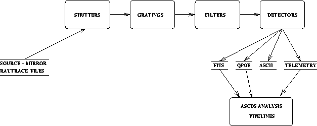
Figure: Simulation Schematic. Original PostScript figure (8kB).
The SHUTTERS module simulates 16 separately configurable shutters
behind the mirror assembly. The GRATINGS module simulates the High,
Medium, and Low Energy Transmission Gratings. The FILTERS module
simulates optical blocking filters in front of the detectors. The
detectors are ACIS ( a charge coupled device) and HRC ( a microchannel
plate).
ACIS is a charge-coupled device optimized for X-ray
detection. Its 24µm pixel size offers ½´´
resolution in the AXAF focal plane. The field of view is
16×16´ for the imaging array and 8×48´ for the
spectroscopic array. The chip is modeled as a multilayer
structure. The incident X-ray photons create a charge cloud
whose position and size are determined by the silicon
absorption depth, the photon energy, the photon position and
the dopant concentration. The charge cloud then drifts to
the surface of the chip under the influence of a layer
dependent electric field, which we model using a Monte Carlo
method. At the surface, the charge is mapped onto a 3×3 pixel
array. The
functional dependence for the number of electrons (ne)
created by an incident X-ray of energy Ex
is given by ne~nx(Ex/ E).
Here, nx is a
function calculated by the Monte Carlo program and =3.65eV
is the energy required to liberate a
charge carrier. Additional features modeled include read
noise, charge transfer inefficiency, bias, gain, and layer
thicknesses. The algorithms used in the CCD simulation are
based on the program XRAYSIM developed by Lumb
et al. (1994), which in turn was based on analytical
calculations by Janesick (1987, 1988) and Hopkinson (1987).
E).
Here, nx is a
function calculated by the Monte Carlo program and =3.65eV
is the energy required to liberate a
charge carrier. Additional features modeled include read
noise, charge transfer inefficiency, bias, gain, and layer
thicknesses. The algorithms used in the CCD simulation are
based on the program XRAYSIM developed by Lumb
et al. (1994), which in turn was based on analytical
calculations by Janesick (1987, 1988) and Hopkinson (1987).
The simulator can be operated in two modes. The Event
List Mode outputs the abovementioned 3×3 pixel array to a
FITS event list. This mode is designed for high throughput
and does not model effects which arise when two photons hit
the same location on the chip in a given integration
period. The Full Frame Mode embeds the 3×3 pixel array
in a much larger rectangular array in memory. This mode includes the
effects which arise when multiple photons hit the same
location in a given integration period. The Full Frame
Mode has two output formats available. The events can be
extracted from the array in memory using the same algorithm
used to detect events in real ACIS frames. The extracted
events are output to a FITS event list. Alternatively, the
full arrays can be written to FITS image files, one for each
integration period. These image files are similar to those
produced by the physical chips before event
extraction. Event detection in the array in memory
yields substantial performance gains over detection of the
events in the FITS image files.
The HRC is a microchannel plate (MCP) detector that provides
a spatial resolution of less than ½´´. The field of
view is 31×31´ for the imaging array and
7×97´ for the spectroscopic array. Resolving power
is limited, with E/ E~1. The
simulation models the UV Ion Shield (UVIS), the MCP itself,
and the wire charge grid. The UVIS is modeled using a
generalized filter program that statistically simulates
photon absorption by applying a transmission curve to the
input photon energy. The MCP surface is modeled as a surface
of circular pores with a diameter of 0.0125mm and spacing of
0.015mm. A model of quantum efficiency
as a function of incident angle is also applied. The wire
grid charge resulting from the charge cloud produced by the
MCP is modeled by a scaled Lorentz function. Events are
passed into a telemetry simulator that models dead time
induced by telemetry bandwidth limitations. Output modes are
raw telemetry, FITS event list, and QPOE image formats.
The HRC simulator has also been adapted to simulate a similar
instrument called the High Speed Imager (HSI) which is used for
telescope mirror calibration.
E~1. The
simulation models the UV Ion Shield (UVIS), the MCP itself,
and the wire charge grid. The UVIS is modeled using a
generalized filter program that statistically simulates
photon absorption by applying a transmission curve to the
input photon energy. The MCP surface is modeled as a surface
of circular pores with a diameter of 0.0125mm and spacing of
0.015mm. A model of quantum efficiency
as a function of incident angle is also applied. The wire
grid charge resulting from the charge cloud produced by the
MCP is modeled by a scaled Lorentz function. Events are
passed into a telemetry simulator that models dead time
induced by telemetry bandwidth limitations. Output modes are
raw telemetry, FITS event list, and QPOE image formats.
The HRC simulator has also been adapted to simulate a similar
instrument called the High Speed Imager (HSI) which is used for
telescope mirror calibration.
The mirror simulation's raytrace output can be projected
directly on to the model detectors, or diffracted by the
gratings module before projection on to the model
detectors. The dispersed gratings spectrum provides a
resolving power of E/E ~ 10 .
The High Energy Transmission Grating is
typically used in conjunction with the ACIS detector and the
Low Energy Transmission Grating with the HRC.
.
The High Energy Transmission Grating is
typically used in conjunction with the ACIS detector and the
Low Energy Transmission Grating with the HRC.
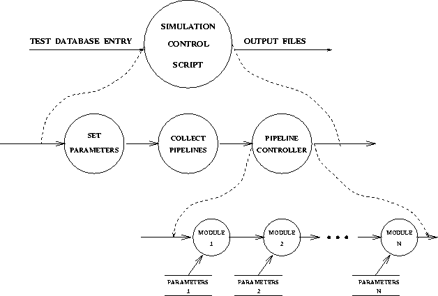
Figure: Simulation Control Hierarchy. The hierarchy of
program control is depicted. Using database entries
describing the test to be performed, parameters describing
the configuration are set. The ASCDS pipeline
controller initiates the raytrace and monitors program
execution. Original PostScript figure (21kB).
The simulator control hierarchy is depicted in Figure 2. The
simulators run as a set of UNIX processes, each of which represents a
physical component being modeled. These processes are started,
monitored, and stopped by the ASCDS Pipeline Controller. The
simulators utilize common ASCDS libraries where possible, such as the
IRAF parameter interface. Events (photons) are passed from one process
in the pipeline to the next with each process performing some
necessary action on an event before passing it along. The action may
be to alter the event or to decide not to propagate it. The
simulators are implemented primarily in C, with some supporting code
written in Perl.
The software is designed to easily accommodate modifications and
enhancements. The modular pipeline approach has facilitated the
interchange of modules as we continue to upgrade the fidelity and
capabilities of the simulations. In order to further improve
flexibility and provide access to data in the simulator pipelines, a
C++ Application Program Interface to the simulator data stream is
being prototyped.
Acknowledgments:
This project is supported by NASA contract NAS8-39073
(ASC). We would like to thank the following individuals for
their contributions to the simulations. Terry Gaetz, Diab
Jerius, and Dan Nguyen developed the mirror and source
models. John Davis, Dan Nguyen, and Mike Wise developed the
gratings model. Diab Jerius developed the HRC pore surface
model. Dave Plummer developed the HRC Telemetry dead time
simulation. Adam Dobrzycki developed the HRC charge grid
algorithm.
References:
Janesick, J. R., Elliot, T., Collins, S.,
Taher, D., Campbell, D., & Garmire, G. 1987, Optical Engineering, 26, 2, 156
Janesick, J. R., Elliot, T., Bredthauer, R.,
Chandler, C., & Burke, B. 1988, SPIE, 982, 70
Hopkinson, G. R. 1987, Optical Engineering, 26, 8, 766
Lumb, D., Townsley, L., Nousek, J., Burrows, D., & Corbet, R., 1994, personal communication
© Copyright 1997 Astronomical Society of the Pacific,
390 Ashton Avenue, San Francisco, California 94112, USA
Next: Modeling AXAF Obstructions with the Generalized Aperture Program.
Previous: Simulated AXAF Observations with MARX
Up: AXAF
Table of Contents - Index - PS reprint
payne@stsci.edu