ALMA Front End
Design Specifications and Requirements
Doc. No.: FEND-40.00.00.00-001-A-SPE
Prepared: Hans Rudolf, ALMA Front End IPT
ESO 2003-02-06
Name Date Signature
Approved:
Name Date Signature
Released:
Name Date Signature
Revision history
Issue |
Approval Date |
Part(s) affected |
Reason/remarks |
1 |
|
All |
First document release |
|
|
|
|
|
|
|
|
|
|
|
|
|
|
|
|
|
|
|
|
|
|
|
|
|
|
|
|
|
|
|
|
|
|
|
|
|
|
|
|
|
|
|
|
|
|
|
|
|
|
|
|
|
|
|
|
|
|
|
|
|
|
|
|
|
|
|
|
|
|
|
|
|
|
|
|
|
|
|
|
1. Introduction
1.1. Purpose
1.2. Scope
1.3. Applicable documents
1.4. Reference documents
1.5. Acronyms
2. Description
2.1. Equipment Definition
2.2. Definition of terms
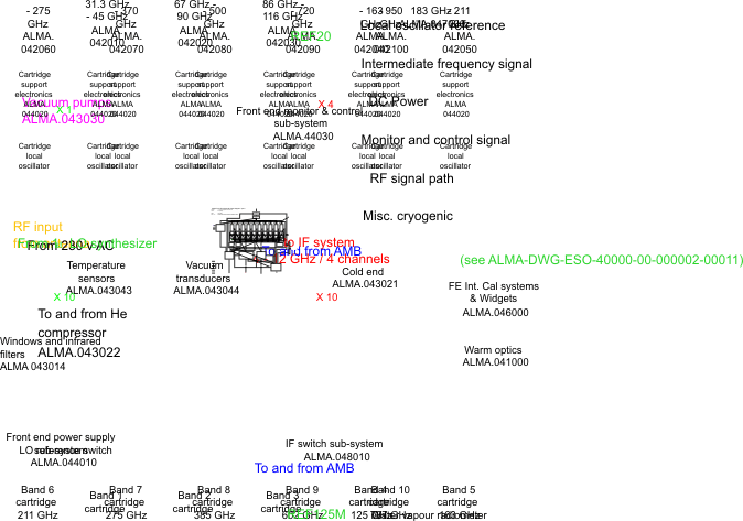
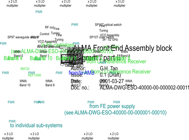
2.3. Block diagram
3. Functional Requirements
3.1. Operation modes
3.1.1. Operational
3.1.2. Non-Operational
3.1.3. Transport with the antenna
3.1.4. Transport in the Front End service vehicle
3.1.5. Storage
3.2. General
3.2.1. Pre-selection of observation bands
3.2.2. Mechanical tuning
3.2.3. Standard parts
3.2.4. Cables and connectors
3.2.5. Solar observing and safety
3.3. Frequency Coverage
3.3.1. RF input port
3.3.2. LO input port
3.3.3. IF output port bandwidth and centre frequency
4. Performance requirements
4.1. Cryogenics, Dewar, and Vacuum
4.1.1. Evacuation and cool-down time
4.1.2. Warm-up time
4.1.3. Re-pump period
4.2. Optics
4.2.1. Polarisation
4.2.1.1. Polarisation Optimisation
4.2.1.2. Polarisation States
4.2.1.3. Polarisation accuracy
4.2.1.4. Cross-Polarisation
4.2.1.5. Polarisation mismatch
4.2.2. Beam pattern / Beam efficiency
4.2.3. Insertion Loss
4.2.4. Pointing stability
4.2.5. Solar Filter
4.2.6. Quarter-Wave-Plate
4.2.7. Amplitude Calibration
4.3. Water Vapour Radiometer
4.3.1. WVR beam accuracy
4.3.2. WVR sensitivity
4.3.3. WVR tuning range and step size
4.3.4. WVR calibration interval
4.4. Front End Noise Performance
4.5. Image Band Suppression / sideband mismatch
4.6. Spurious response of the receiver
4.7. Out-of band response
4.8. Saturation
4.9. Gain
4.10. Gain stability
4.11. Group Delay
5. Mechanical and electrical Requirements
5.1. Mass
5.2. Centre of Gravity
5.3. Volume
5.4. Orientation
5.5. Thermal Load
5.6. Power requirements
6. operating conditions
6.1. Stabilisation time
6.2. Simultaneous operation of bands
6.3. Band Selection
6.3.1. Selection of a (pre-set) observing band
6.3.2. Selection of new observing band
6.3.3. Narrow-band frequency switching
6.3.4. Frequency changes within a band
6.4. Local Oscillator
6.4.1. LO phase stability
6.4.2. LO step size
6.4.3. LO Phase switch time
6.5. Monitoring and Control
6.6. Environmental operating conditions
6.6.1. Altitude
6.6.2. Thermal Environment
6.6.3. Relative Humidity
6.6.4. Vibration
6.6.5. Acceleration-
6.6.6. Cleanliness
6.7. Storage and shipping conditions
6.8. EMC
6.8.1. RFI
6.9. Grounding / Isolation
6.10. Availability, reliability and maintainability
6.10.1. MTBF
6.10.2. MTTR
6.10.3. Lifetime
6.10.4. Maintenance
6.10.5. Hold times
This document summarizes the key design specifications and requirements for the Front End.
It has been prepared for the detailed design of the ALMA Front End in ALMA phase 2.
The information given in this document provides a complete summary of all the requirements and specifications that must be met by the Front End design. The specifications are given in a “black box” view. This document is accompanied by the specifications of the Front End units and Interface Control Documents for the Form End.
The following table shows a partial view of the ALMA product tree [1] at “module” and “unit” level for the ALMA Front End products that are covered by this document. Those products belonging to the FE sub-system which are not specified by this document are clearly identified in the following table.
PT level 1 / “sub-system” |
PT level 2 / “module” |
PT level 3 / “unit” |
|
|||
Product No. |
Product Name |
Product No. |
Product Name |
Product No. |
Product Name |
Remarks |
40.00.00.00 |
Front end |
|
|
|
|
|
|
|
40.01.00.00 |
Warm optics |
|
|
|
|
|
40.02.00.00 |
Cartridges |
|
|
|
|
|
|
|
40.02.01.00 |
Frequency band 1 cartridge |
|
|
|
|
|
40.02.02.00 |
Frequency band 2 cartridge |
|
|
|
|
|
40.02.03.00 |
Frequency band 3 cartridge |
|
|
|
|
|
40.02.04.00 |
Frequency band 4 cartridge |
|
|
|
|
|
40.02.05.00 |
Frequency band 5 cartridge |
|
|
|
|
|
40.02.06.00 |
Frequency band 6 cartridge |
|
|
|
|
|
40.02.07.00 |
Frequency band 7 cartridge |
|
|
|
|
|
40.02.08.00 |
Frequency band 8 cartridge |
|
|
|
|
|
40.02.09.00 |
Frequency band 9 cartridge |
|
|
|
|
|
40.02.10.00 |
Frequency band 10 cartridge |
|
|
|
40.03.00.00 |
Cryostat |
|
|
|
|
|
|
|
40.03.01.00 |
Dewar |
|
|
|
|
|
40.03.02.00 |
Cryo-cooler |
|
|
|
|
|
40.03.03.00 |
Vacuum pumps |
|
|
|
|
|
40.03.04.00 |
Cryostat electrical infrastructure |
|
|
|
40.04.00.00 |
Front end auxiliary sub-systems |
|
|
|
|
|
|
|
40.04.01.00 |
Front end power supply sub-system |
|
|
|
|
|
40.04.02.00 |
Bias electronics sub-system |
|
|
|
|
|
40.04.03.00 |
Front end M&C sub-system |
|
|
|
40.05.00.00 |
Front end chassis |
|
|
|
PT level 1 / “sub-system” |
PT level 2 / “module” |
PT level 3 / “unit” |
|
|||
Product No. |
Product Name |
Product No. |
Product Name |
Product No. |
Product Name |
Product No. |
|
|
|
|
40.05.01.00 |
Front end mechanical structure |
|
|
|
|
|
40.05.02.00 |
Front end cabling |
|
|
|
40.06.00.00 |
Front end integrated calibration & widgets |
|
|
|
|
|
|
|
40.06.01.00 |
Vane calibration sub-system |
|
|
|
|
|
40.06.02.00 |
Solar protection |
|
|
|
|
|
40.06.03.00 |
Polarisation widgets |
|
|
|
40.07.00.00 |
Water vapour radiometer |
|
|
|
|
|
40.08.00.00 |
Front end IF |
|
|
|
|
|
|
|
40.08.01.00 |
IF switch sub-system |
|
|
|
40.09.00.00 |
Front end specific test, construction & service equipment |
|
|
Not covered in this document |
|
|
|
|
40.09.01.00 |
SIS mixer fabrication equipment |
Not covered in this document |
|
|
|
|
40.09.02.00 |
SIS mixer test equipment |
Not covered in this document |
|
|
|
|
40.09.03.00 |
Front end test fixture |
Not covered in this document |
|
|
|
|
40.09.04.00 |
Cartridge test dewars |
Not covered in this document |
|
|
|
|
40.09.05.00 |
Cartridge RF test fixtures |
Not covered in this document |
|
|
|
|
40.09.06.00 |
Front end service vehicle |
Not covered in this document |
|
|
40.10.00.00 |
First local oscillator |
|
|
|
|
|
|
|
40.10.01.00 |
First LO frequency sources |
|
|
|
|
|
40.10.02.00 |
Warm frequency multipliers |
|
|
|
|
|
40.10.03.00 |
First LO PLL unit |
|
|
|
|
|
40.10.04.00 |
Band selection |
|
The following documents are part of this document to the extent specified herein. If not explicitly stated differently, the latest issue of the document is valid.
Reference |
Document title |
Document ID |
||
[AD1] |
ALMA Product Tree |
SYSE-80.03.00.00-001H-LIS |
||
[AD2] |
ALMA Equipment Shipping & Storage Environmental Specification |
ALMA-80.05.02.00-004-A-SPE |
||
[AD3] |
ALMA system wide requirements – Electromagnetic Compatibility |
ALM-SPE-ESO-12000-00007 |
||
[AD4] |
ICD |
Antenna |
Front End |
(in preparation) |
[AD5] |
ICD |
Front End |
Back End |
(in preparation) |
[AD6] |
ICD |
Front End |
Computing |
(in preparation) |
[AD6] |
ICD |
Site |
Front End |
(in preparation) |
[AD7] |
ALMA Electrical Design Specification |
ALMA-SPE-ESO-10000-0015 |
||
[AD8] |
ALMA Power Quality Specification |
SYSE-80.05.00.00-001A-SPE |
||
|
|
|
||
In the event of a conflict between one of the before mentioned applicable documents and the contents of this document, the contents of this document shall be considered as a superseding requirement.
The following documents contain additional information and are referenced in this document.
Reference |
Document title |
Document ID |
[1] |
List of acronyms and glossary for the ALMA project |
(in preparation) |
[2] |
ALMA Project Book |
|
[3] |
ALMA Receiver Optics Design |
ALMA Memo #362 |
[4] |
Lifetime Definitions of ALMA Products |
SYSE-80.05.00.00-002A-SPE |
A limited set of basic acronyms used in this document is given below. A complete set of acronyms used in the ALMA project can be found in reference [1].
ALMA Atacama Large Millimeter Array
CDR Critical Design Review
DSB Double-SideBand
ICD Interface Control Document
PDR Preliminary Design Review
SSB Single-SideBand
2SB Dual-SideBand separating
FESS Front End Support Structure
The front end (FE) assembly accepts the focused beam from the antenna's secondary reflector over a selected band of frequencies. It amplifies and converts this band to an intermediate frequency band in several channels (typically differing in polarisation and/or sideband), and delivers the IF signals as outputs. It accepts as inputs local oscillator reference signals at the appropriate frequencies and levels to generate the local oscillator signal for conversion. The front end assembly includes:
· RF optics as required to couple the sub-reflector beam to its first electronic element.
· Mixers and amplifiers of the RF-IF signal path (separately for each band required to cover the overall frequency range), including any components needed to couple the LO signal to each mixer.
· Local oscillator components within the cryostat and associated hardware. The interface between the LO subsystem and the Front End subsystem is at the waveguide input to the warm multiplier assembly at a frequency of around 100 GHz. Each cartridge will have its own interface to the LO sub system. The interface will be specified in detail in a corresponding ICD.
· Vacuum system and cryo-coolers needed to achieve the appropriate operating temperatures for certain components, along with related thermal insulation and mechanical supports.
· Bias and control circuits to support the RF-IF amplifiers and mixers.
· Devices to select the desired frequency, including IF band switching and any required tuning or adjustment of amplifiers and mixers as a function of frequency.
· A monitor/control system allowing remote control of all functions and providing extensive remote diagnosis capability, with an appropriate interface to the general ALMA monitor and control bus. The implementation of such a system will be decided between the front-end, systems and software groups and corresponding ICDs developed.
· A water-vapour monitoring radiometer.
· Devices that are placed directly in the input beam of the receiver and which include (but are not limited to) calibration systems, insertable components such as quarter wave plates for circular polarisation, and attenuators for solar observations.
It does not include the following elements, which belong to other subsystems:
· the local oscillator subsystem up to the agreed interface (see ICD),
· general power supplies (which are part of the common infrastructure), and
· calibration devices located outside the receiver cabin (including any built into the sub-reflector).
· Front end assembly: this is the front end subsystem as defined in 2.1. It provides space for 10 cartridges (see below).
· Band: this is the range of RF frequencies which is received in dual linear polarisation and defined in 3.3.1.
· Frequency channel: this is one receiving chain which receives one polarisation within the specified band. A band has two channels.
· Cartridge: a device insertable into the main dewar, receiving RF frequencies within one specified band in dual polarisation, containing optics, mixers, IF amplifiers, LO components. Receives the RF from external optics, accepts an LO signal, and delivers IF signals.
· ICD: Interface Control Document. The document which specifies interfaces between subsystems and parts within a subsystem.
The ALMA Front End shall be used with the following operation modes.
FEND-91010-ZZZ
This mode is used during observation with the antenna on which the front end is mounted. For this mode, all specifications and requirements in this document apply, unless otherwise stated. The operational mode is also called “On”.
FEND-91020-ZZZ
This mode is used when the antenna on which the front end is mounted is not used for observation. Therefore it is also called “Off”.
3.1.3.Transport with the antenna
FEND-91030-ZZZ
This mode is used, when the Front End is transported with the antenna on the antenna transport vehicle. This mode differs from the Non-operational mode basically in the environmental operating conditions. For this mode, the same specifications and requirements as for the non-operational mode apply, unless otherwise stated.
3.1.4.Transport in the Front End service vehicle
FEND-91040-ZZZ
This mode is used, when the front end is transported with the front end service vehicle. This mode differs from the Non-operational mode basically in the environmental operating conditions. For this mode, the same specifications and requirements as for the non-operational mode apply, unless otherwise stated.
FEND-91050-ZZZ
Though not being an operational mode, the ALMA front end may be stored completely assembled. This mode differs from the Non-operational mode basically in the environmental conditions and the lack of monitoring and control signals. For storage, the same specifications and requirements as for the non-operational mode apply, unless otherwise stated.
3.2.1.Pre-selection of observation bands
FEND-92110-ZZZ
Means shall be provided to pre-select observation bands. This applies only to the operational mode.
FEND-92020-ZZZ
No mechanical tuning shall be employed.
FEND-92030-ZZZ
Standard, unmodified commercially available components shall be used where possible.
FEND-92040-ZZZ
All cables and connectors shall be uniquely identified and labelled (ALMA standard ???) and be clearly visible and non removable. Nomenclature shall be identical to that used in the documentation.
Keyed and unique connectors shall be used to prevent accidental connector swapping, wherever possible. Exterior connectors shall be rugged (mil spec/) and protected from dust.
3.2.5.Solar observing and safety
FEND-62910-ZZZ
No components shall be damaged if the receiver input is illuminated by 0.3 W/cm2 of solar optical and infrared radiation. Provisions shall be taken to allow observations of the sun.
This section applies only to the operational mode.
Band |
Start frequency |
Stop frequency |
Remarks |
|
1 |
31.3 GHz |
45 GHz |
|
FEND-21310-ZZZ |
2 |
67 GHz |
90 GHz |
|
FEND-22310-ZZZ |
3 |
86 GHz |
116 GHz |
tunable to 84 GHz |
FEND-23310-ZZZ |
4 |
125 GHz |
163 GHz |
|
FEND-24310-ZZZ |
5 |
163 GHz |
211 GHz |
|
FEND-25310-ZZZ |
6 |
211 GHz |
275 GHz |
|
FEND-26310-ZZZ |
7 |
275 GHz |
370 GHz |
tunable to 372 GHz |
FEND-27310-ZZZ |
8 |
385 GHz |
500 GHz |
|
FEND-28310-ZZZ |
9 |
602 GHz |
720 GHz |
|
FEND-29310-ZZZ |
10 |
787 GHz |
950 GHz |
|
FEND-20310-ZZZ |
Band |
Bottom frequency |
Top frequency |
Remarks |
|
1 |
27.3 GHz |
33 GHz |
USB mixing scheme |
FEND-21320-ZZZ |
2 |
79 GHz |
94 GHz |
LSB mixing scheme |
FEND-22320-ZZZ |
3 |
94 GHz |
108 GHz |
tunable to 92 GHz |
FEND-23320-ZZZ |
4 |
133 GHz |
155 GHz |
|
FEND-24320-ZZZ |
5 |
171 GHz |
203 GHz |
|
FEND-25320-ZZZ |
6 |
219 GHz |
267 GHz |
|
FEND-26320-ZZZ |
7 |
283 GHz |
362 GHz |
tunable to 364 GHz |
FEND-27320-ZZZ |
8 |
393 GHz |
492 GHz |
|
FEND-28320-ZZZ |
9 |
610 GHz |
712 GHz |
|
FEND-29320-ZZZ |
10 |
795 GHz |
942 GHz |
|
FEND-20320-ZZZ |
3.3.3.IF output port bandwidth and centre frequency
FEND-80310-ZZZ
Each frequency channel shall provide 8 GHz total IF bandwidth per polarisation using one of the following alternatives depending on the mixing scheme selected:
o 8 GHz bandwidth single-sideband (SSB), upper or lower sideband centred at 8.0 GHz
o 8 GHz bandwidth double-sideband (DSB), centred at 8.0 GHz
o 4 GHz bandwidth dual-sideband, (2SB) upper and lower sideband, centred at 6.0 GHz
2.1. Cryogenics, Dewar, and Vacuum
2.1.1.Evacuation and cool-down time
FEND-32610-ZZZ
The dewar with all cartridges being installed shall be ready for operation in maximum 48 hours (TBC), with the use of an external pump.
FEND-32620-ZZZ
The warm-up of the dewar to ambient temperature shall be performed in maximum 6 hours.
FEND-33610-ZZZ
Periodic re-pumping shall be performed in intervals of minimum 12 months.
This section applies only to the operational mode.
2.2.1.1. Polarisation Optimisation
FEND-11010-ZZZ
The polarisation performance shall be optimised for band 7.
FEND-11110-ZZZ
The front end shall simultaneously receive two orthogonal polarisations, with each converted to one or more separate IF outputs depending on mixing scheme. The nominal polarisation states shall be linear.
2.2.1.3. Polarisation accuracy
FEND-11210-ZZZ
The polarisation alignment, including the inter-antenna polarisation alignment shall be better than 2o.
FEND-11310-ZZZ
At any frequency within the front end's tuning range, the polarisation states of the two channels should conform to a maximum cross-polarisation of -20 dB, measured at the optical entrance to the front end subsystem.
2.2.1.5. Polarisation mismatch
FEND-11410-ZZZ
The front end contribution to the maximum polarisation mismatch between any pair of antennas in the array shall not exceed -20 dB.
2.2.2.Beam pattern / Beam efficiency
FEND-12010-ZZZ
The beam efficiency for all frequency bands and both receive polarisations shall exceed 90 % (TBC). This beam efficiency comprises all optic elements that belong to the front end.
FEND-13010-ZZZ
The optical coupling of each front end channel to the telescope shall be maximized. Details can be found in [3].
FEND-14010-ZZZ
The pointing stability on tipping shall be smaller than 2 arcsecs.
FEND-62920-ZZZ
A solar filter shall be provided for solar observations. The solar filter shall provide a remotely controlled automatic insertion into the beam. It shall provide a 20 dB attenuation of a 10 micron radiation and an attenuation of 13 dB for the RF of all ALMA frequency bands.
FEND-64010-ZZZ
A quarter wave plate shall be foreseen for band 7. The centre frequency of the quarter wave
plate shall be TBD GHz, its loss shall be less than TBD dB.
![]()
FEND-65010-ZZZ
Means for periodic amplitude calibration shall be provided. Calibration shall be completed in a time not to exceed 2 sec. The calibration shall give an amplitude accuracy of not less than 1 % (TBC).
FEND-70910-ZZZ
The front end shall include a radiometer for measurement of water vapour along the signal path, using the 183 GHz line. This instrument shall operate simultaneously with the selected astronomy band illuminating the sub-reflector. It must include all necessary LO sources and signal processing.
It shall have a tunable LO frequency.
FEND-70920-ZZZ
This subsection applies only to the operational mode.
The beam position of the WVR relative to the observing band shall be within 10 arcmin.
FEND-70930-ZZZ
This subsection applies only to the operational mode.
The rms path error of the WVR shall be less than 10*(1+wv) μm of path, with wv being the water vapour along the line of sight in millimetres. This sensitivity shall be achieved with a time resolution of 1 second and shall be maintained over time periods of 5 minutes and for changes in zenith angle of up to 1 degree.
2.3.3.WVR tuning range and step size
FEND-70310-ZZZ
This subsection applies only to the operational mode.
The tuning range of the WVR shall be not less than 25 MHz (TBC), allowing for tuning steps of not bigger than 25 kHz (TBC).
2.3.4.WVR calibration interval
FEND-70610-ZZZ
This subsection applies only to the operational mode.
The calibration interval of the WVR shall be 5 mins.
2.4. Front End Noise Performance
This section applies only to the operational mode,
The following table shows the required noise temperature performance of the ALMA Front End. The noise performance is referred to its RF input port, with the contributions from warm optics, dewar windows, and IR filters. It must take into account all the noise contributions up to the cartridge IF output ports.
Depending on the selected mixer scheme the cartridge noise temperature shall not exceed the values of either TSSB for SSB and 2SB response or TDSB = 0.5.TSSB for DSB responses as follows:
Table: Specifications for maximum receiver noise temperatures
Band |
SSB |
DSB |
|
||
T(SSB) over 80% of the RF band |
T(SSB) at any RF frequency |
T(DSB) over 80% of the RF band |
T(DSB) at any RF frequency |
||
1 |
15 K |
23 K |
8 K |
12 K |
FEND-21910-ZZZ |
2 |
28 K |
43 K |
14 K |
22 K |
FEND-22910-ZZZ |
3 |
34 K |
54 K |
17 K |
27 K |
FEND-23910-ZZZ |
4 |
47 K |
76 K |
24 K |
38 K |
FEND-24910-ZZZ |
5 |
60 K |
98 K |
30 K |
49 K |
FEND-25910-ZZZ |
6 |
77 K |
126 K |
39 K |
63 K |
FEND-26910-ZZZ |
7 |
133 K |
198 K |
67 K |
99 K |
FEND-27910-ZZZ |
8 |
181 K |
270 K |
91 K |
135 K |
FEND-28910-ZZZ |
9 |
335 K |
500 K |
168 K |
250 K |
FEND-29910-ZZZ |
10 |
438 K |
655 K |
219 K |
328 K |
FEND-20910-ZZZ |
Remarks:
· Frequency and frequency range in the table above as specified in section 3.3.1 of this document.
· The noise temperatures shall be reached for the full IF band, as defined in section 3.3.3
· The noise temperatures in this table are based on the approved “Specifications for the ALMA Front End Assembly”, version 1.0, and the following.
· The noise temperature shall be calculated from measurements according to the Rayleigh-Jeans law.
· Following an ASAC recommendation the values in the Table were calculated with the following formula:
T(SSB)= A * (h*freq/k) + 4 K
where h and k are the usual physical constants, and freq was taken as the centre frequency of a particular band. The frequency dependent quantity A has the following specification and values (over 80% of the RF band / at any freq):
Bands 1-6 (below 275 GHz) Spec: A = 6 / 10
Bands 7-8 (275-500 GHz) Spec: A = 8 / 12
Band 9 (602-720 GHz) Spec: A = 10 / 15
Band 10 (787-950 GHz) Spec: A = 10 / 15
5.1. Image Band Suppression / sideband mismatch
FEND-80910-ZZZ
This section applies only to the operational mode.
If either a SSB or 2SB mixing scheme is selected at least 10 dB image band suppression shall be provided.
If a DSB mixing scheme is selected, the side-band ratio shall be 3 dB or better.
5.2. Spurious response of the receiver
FEND-80920-ZZZ
This section applies only to the operational mode.
The in-band spurious response of the receiver shall be less than 3 dB over nominal IF output power spectral density.
FEND-80930-ZZZ
This section applies only to the operational mode.
For a 2SB mixing scheme all signals in the 8-12 GHz frequency range at the IF port shall not exceed a power level of -50 dBm (TBC).
FEND-80940-ZZZ
This section applies only to the operational mode.
The saturation level shall not exceed 1% gain compression (bands 1-6) and 3% gain compression (bands 7-10), respectively, for any DT of not less than 300 K above TSys at the RF input port.
FEND-80950-ZZZ
This section applies only to the operational mode.
The IF shall be delivered within a power range of -40 dBm/GHz to -27 dBm/GHz spectral power from 4 to 12 GHz, with a maximum total power of -18 dBm from 4 to 12 GHz and -15 dBm from 10 MHz to 18 GHz..
The gain-flatness shall be maximum +/- 1.5 dB (TBC) over the complete IF band, at any RF
frequency.
![]() The gain-slope shall be TBD.
The gain-slope shall be TBD.
FEND-80960-ZZZ
This section applies only to the operational mode.
Variations in gain, as specified in section 4.9, as a function of time should comply with the following:
Application |
Power Gain Variation (RMS) |
Single dish observation |
10-4 (TBC) over 1sec |
Interferometer |
3x10⁻³ (TBC) over 60 secs |
Differential |
5x10⁻⁴ (TBC) over 1 sec |
FEND-80970-ZZZ
This section applies only to the operational mode.
The nominal cartridge group delay measure from RF input port to IF output port shall be within
the range TBD to TBD. The
![]() nominal value is obtained for the mid-band RF input frequency
and the mid-band IF output frequency.
nominal value is obtained for the mid-band RF input frequency
and the mid-band IF output frequency.
Variations as a function of RF and IF frequencies, slope and ripple, are to be determined.
6. Mechanical and electrical Requirements
FEND-93010-ZZZ
The ALMA Front End, including all components as presented in figure 1 of this document, shall not exceed a mass of 750 kg.
Details can be found in the appertaining ICD [AD4].
FEND-93020-ZZZ
The centre of gravity of the Front End dewar shall be at 400 mm +/- 400 mm below the FESS.
![]() FEND-93030-ZZZ
FEND-93030-ZZZ
All Front End components with the product numbers 40.01.xx.xx, 40.02.xx.xx, 40.03.01.xx, 40.03.02.01, 40.03.03.xx, 40.03.04.xx, 40.04.02.xx, 40.04.03.xx, 40.05.xx.xx, 40.07.xx.xx 40.08.xx.xx, and 40.10.xx.xx shall altogether remain within a volume of 1600 mm x 1000 mm x 1000 mm (TBC).
Front End components that will be placed in the volume above the dewar (40.06.xx.xx) shall not extend beyond a volume of TBD x TBD x TBD.
The compressor (40.03.02.02) shall not extend beyond a volume of 500 mm x 250 mm x 1600 mm (TBC).
The indoor control unit (40.03.02.03) shall not extend beyond a volume of TBD x TBD x TBD.
Details can be found in the appertaining ICD [AD4].
FEND-93040-ZZZ
The front end shall meet all performance requirements over a range of gravity vectors from 0 (TBC) to 90 (TBC) degrees. This rotation occurs about the antenna elevation-bearing axis.
Details can be found in the appertaining ICD [AD4].
The compressor shall keep the dewar at the specified temperature at tilt angles not exceeding 10o.
FEND-93050-ZZZ
The maximum thermal load presented by the Front End in the operational mode shall not exceed 4 kW for all items except the cryo-cooler and the compressor (TBC).
Details can be found in the appertaining ICD [AD4].
FEND-93060-ZZZ
The ALMA front components within the receiver cabin shall not consume more than 4 kW of mains-power in the operational mode. The front components outside the receiver cabin (compressor) shall not consume more than 10 kW of mains-power. Details can be found in the appertaining ICD [AD4].
The supplied single-phase 230 VAC/50 Hz and three-phase 400 VAC/50 Hz power shall comply with [AD8].
FEND-92120-ZZZ
Starting from the non-operational mode, the front end shall reach the operational mode within 15 minutes.
100 ms (TBC) after the conclusion of fast-slew, the front end specifications shall be met for the operating front end.
7.2. Simultaneous operation of bands
FEND-92130-ZZZ
This section applies only to the operational mode.
Astronomical observations will be done in only one frequency band at any one time (no dual frequency observations). The water-vapour monitoring radiometer shall operate simultaneously with any of the observing bands.
When band 3 is not used for observation, it shall be always on stand-by. In addition to that, one more band can be on stand-by.
This section applies only to the operational mode.
7.3.1.Selection of a (pre-set) observing band
FEND-92140-ZZZ
Selection and operation of a pre-set (i.e. switched on and tuned) observing band shall be possible in less than 1.5 sec. This provides support for fast phase-switching and switching to another (pre-set) observing band. The reselection of a particular frequency band at a particular antenna shall result in pointing errors not to exceed 0.2".
7.3.2.Selection of new observing band
FEND-92150-ZZZ
Switching to a new observing band shall be possible in less than 1.5 sec if the electronics of this particular observing band has been switched on the time twarm-up before using the band. twarm-up shall not exceed 15 min, and a much shorter time is desirable. This is to reach thermal equilibrium and maximum stability.
7.3.3.Narrow-band frequency switching
FEND-92160-ZZZ
Changing between two frequencies within .03% of each other (30 MHz at 100 GHz, 285 MHz at 950 GHz) and in the same band shall require no more than 10 msec. This provides support for narrow-band frequency switching.
7.3.4.Frequency changes within a band
FEND-92170-ZZZ
Changing between frequencies more than .03% apart and in the same band shall not require more than 5 sec.
This subsection does only apply to the operational mode.
FEND-03510-ZZZ
Phase stability (both short and long term – jitter/drift)63fs and 29 fs
FEND-03310-ZZZ
The first LO shall have a step size smaller than TBD
![]() kHz.
kHz.
FEND-03610-ZZZ
The LO shall switch the phase by 180o every 256 us and by 90o every 16 ms. Each of those phase switches shall be done in 1 us or faster.
FEND-43910-ZZZ
All functions in the FE shall be able to be remotely controlled. Sufficient monitoring shall be provided to indicate the status of the FE and to support preliminary diagnosis for the FE in case of failure. This section applies not for the storage mode. Details can be found in the appertaining ICD [AD6].
7.6. Environmental operating conditions
![]() FEND-92210-ZZZ
FEND-92210-ZZZ
This subsection does not apply for the transport modes and for the storage mode.
The Front End shall meet its performance at an altitude of 5000m.
The front end shall meet its performance for a room temperature of 16o C to 22o C. The required temperature variation shall not exceed +/- 1o C peak-to-peak.
The front end shall survive room temperatures of -10o C to 50o C (TBC) without damage to the equipment.
The Front End shall meet its performance with a relative humidity between 20 % (TBC) and 80 %.
For the transport with the antenna mode, the front end shall withstand vibrations with a PSD of 1x10⁻⁵ g2/Hz from 20-1000 Hz, 6 dB/octave roll-off to 2000 Hz (TBC).
For the transport with the front end service vehicle, the front end shall withstand vibrations with a PSD of 1x10⁻⁵ g2/Hz from 20-1000 Hz, 6 dB/octave roll-off to 2000 Hz (TBC).
For both transport modes and the storage mode, the front end shall withstand accelerations of 4g / -2g for TBD sec.
The maximum slew rate shall be 6 deg/sec and 12 deg/sec2 on both axes for the operational and non-operational mode.
The maximum seismic acceleration shall be 0.3 g on the horizontal axis and 0.3 g on the vertical axis.
The Front End shall meet its performance at a cleanliness of TBD.
7.7. Storage and shipping conditions
FEND-92220-ZZZ
The front end shall comply with [AD2].
This section applies only to the storage mode.
FEND-92230-ZZZ
The front end shall comply with [AD3].
FEND-92240-ZZZ
More than 30 dB isolation in IF between operational and stand-by frequency bands shall be provided.
The emission of the cartridges in the 175-191 GHz range shall be at least 10 dB less than the WVR signal level.
The RF emission of the WVR shall be at least 10 dB less than the cartridge signal level.
FEND-92250-ZZZ
The front end shall be grounded in compliance with
![]() .
.
7.10. Availability, reliability and maintainability
FEND-92310-ZZZ
The front end shall be designed for continuous use. Details can be found in [4].
FEND-92320-ZZZ
The MTBF of the front end shall exceed 5 years (TBC).
FEND-92330-ZZZ
The MTTR of the front end sub-system shall be less than 24 hours (TBC) once all components have reached room temperature.
FEND-92340-ZZZ
The lifetime of the front end shall be class 2 (15 years).
FEND-92350-ZZZ
There shall be no periodic maintenance for any of the front end items. Exceptions can be made upon approval from the front end IPT.
The maintenance interval for the cryo-cooler shall not be shorter than 10.000 hours.
The maintenance interval for the compressor shall not be shorter than 20.000 hours.
FEND-92360-ZZZ
The Front End shall be able to allow for a power interruption of 30 minutes maximum duration. After return of power it shall be able to return to the normal within 6 hours.