 Bow-Tie4
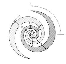 Equiangular4
ALMA Construction Project Book, Chapter 3 Section 2.
Revision History
Summary
In this section, hardware solutions to the problem of calibrating the ALMA amplitude and phase are described. Both solutions use the blocked area in the center of the subreflector as the source of radiation from either a two-temperature load or a coherent signal source. A simple mirror mechanism is used to select between the two systems. The coherent source may be made phase stable through a round-trip measurement scheme so raising the possibility of continuous phase measurement and correction as well as providing a valuable trouble shooting tool.
The details are still (February 2001) under discussion between the
international partners. This chapter is taken with minor changes from
Chapter 3.2 of the original MMA project book. As calibration plans
for the international ALMA project become more certain, the content
will be updated. Although the 2-temperature load scheme presented here
is the baseline plan, alternative chopped-load designs are still actively
being considered; for example a semi-transparent vane. If further study
indicates this to be an advantageous option, the concept may be tested
on the Test Interferometer in 2002-2003.
3.2.1 Introduction
The previous section describes a number of schemes for calibrating the ALMA amplitude and phase. This section outlines two specific hardware schemes which can help to calibrate the instrumental phase and amplitude of ALMA. Other instrumental calibration schemes, such as round-trip phase calibration for the local oscillator, and AGC/total power monitors in the I.F. chain, are described elsewhere.
The two calibration schemes outlined here are:
Absolute amplitude calibration, which represents the
conversion of total power signals from the radio astronomy receivers
to calibrated antenna temperatures, and Relative amplitude and
phase calibration, with an artificial coherent calibration signal
suitable for interferometric calibration
3.2.2 Absolute Amplitude Calibration
It has been suggested by Jack Welch and others, and is currently
the subject of a joint MDC development between BIMA and NRAO. It gives
an absolutely calibrated signal of a few K at the receiver, over the
complete frequency range covered by the ALMA. This system has been
described in MMA
Memo 225 by Bock, Welch, Flemming and Thornton.
The essence of this technique is that a black body radiator is
placed at the center of the subreflector of each antenna, within the
unused area of subreflector matching the central blockage of the
antenna. In this way there is no effect on antenna sensitivity.
Within this central part of the subreflector, a plane mirror
switches between two (or more) loads of different
temperatures. The two loads have very precisely controlled and
calibrated temperatures. The total power output of the receiver is
sampled synchronously with the mirror switching between the two
calibrated loads.
The added switched receiver noise is, to a first approximation,
equal to the difference in temperature of the two hot loads,
multiplied by the beam solid angle of the absorbers at the
subreflector seen from the receiver feed, divided by the beam solid
angle of the subreflector - assuming the receiver feed itself is
matched to the angle subtended by the receiver. This ratio will be
reasonably constant with frequency, but at a given frequency can be
calibrated precisely by measurements of the feed antenn a pattern.
For more details see the memo by Bock, Welch, Flemming and
Thornton. The joint development with BIMA will show, on a timescale of
a few months, how well the technique can be expected to work in
practice.
3.2.3 Relative phase and amplitude calibration
In the debugging stage of the ALMA, there will be a need for a
generic test signal that can be used to debug the entire electronic
system of a given antenna or antenna pair, from front-end to
correlator. When the antenna surface and pointing are sufficiently
reliable, astronomical sources can be used for this purpose, but
having an independent, artificially generated signal that is not
dependent on antenna performance will be invaluable in checking out
and maintaining the system.
If the calibration signal can be made coherent at all individual
antennas, it opens up the possibility of calibrating the entire
receiver system, front-ends, back-ends and correlator, amplitude and
phase as a function of frequency, in a way independent of antenna
tracking, pointing, or efficiency performance. The calibration system
should be sufficiently stable that it can be used as a secondary
calibration system, with only occasional cross-calibration with
astronomical sources.
3.2.4 The Photonic Calibration System
3.2.4.1 Introduction
The photonic calibration system has a broad-band, radiating antenna situated at the center of the subreflector, where no extra antenna blockage is introduced. At the feed of the broadband antenna, there is an uncooled photomixer device. A single optica l fiber, carrying laser signals generated at a central laboratory or control room, feeds this photomixer. In the simplest form, the optical signal would come from two lasers, whose difference frequency corresponds to the telescope observing frequency, and which is phase-locked to the telescope frequency standard. The equipment required to do this would be nearly identical to that being developed for the photonic laser local oscillator system. Only one pair of lasers would be required for the entire array; the combined laser output would be split optically N ways (where N is the number of antennas) and routed via N independent fibers to each antenna.
In slight variants of this scheme, either a single laser signal, or the dual laser system tuned to the required mm-wave difference frequency, could be modulated. The modulation might take the form of a regular comb spectrum, simulating broadband noise.
This becomes quite analogous to the pulse cal system developed for the VLBA, and could be used for checking the relative amplitude and phase response over the entire interferometric IF passband. The modulation might also be a truly random, or a pseudo-ra
ndom digitally generated sequence, which would also provide a broad-band coherent test signal. This random or pseudo-random noise needs to be coherent at each antenna, so timing considerations, within a fraction of the reciprocal bandwidth, are important.
Naturally this injected signal needs to be stable, both in
amplitude and phase. It may require round-trip delay
compensation of some type, and perhaps an AGC system to keep the
signal amplitude constant. However, attention to the stability
of this cali bration signal may relax the technical requirements
elsewhere in the system.
Most of the
development for this coherent photonic calibration scheme is
already being undertaken in the context of the photonic local
oscillator development. The calibration scheme should in
principle be much simpler, because several orders of magnitu de
lower radiated mm-wave power is required. The main additional
development needed is that of the broad-band radiating antenna,
to be sited at the subreflector, fed by the signal from the
photomixer.
3.2.4.2 Requirements
The first thing we did was evaluate the minimum power required at the receiver. The total noise power (PN) for a receiver with system temperature (Tsys) of 100 K and observation bandwidth (Dn) of 2 GHz is given by
PN = kTsysDn = 2.76 10-12 W = -85.6 dBm
We want the received calibration power to be at least 1% of the total noise power: 2.76 10-14 W = -105.6 dBm.
Another requirement is that the injected signal should be linearly polarized at 45 deg with respect to the OMT or polarization grids inside the receiver so that the power is equally distributed into the two channels.
As this
signal should work as a reference we need its characteristics to
be as constant as possible in the whole spectral range we are
going to use it: 100 GHz - 1 THz.
3.2.4.3 Review of antennas for radiating the signal
The best way to launch the signal towards the receiver is use an antenna placed in the blind spot of the subreflector.
As we look at the requirements, we need an antenna with the following characteristics:
There are few antennas that fit these requirements. We focused our attention on the self-similar and self-complementary planar antennas.
The self-similarity is the geometric property of invariance under a uniform expansion or reduction of size. This property implies the absence of any characteristic length scale so that the geometry is entirely defined in term of angles. This guarantees the broad bandwidth.
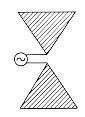
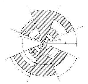
There are several type of self-complementary and self-similar planar antennas: Bow-Tie, Equiangular Spiral and Log-Periodic.
Bow-Tie4Equiangular4
 Log-Periodic4
The Bow-Tie is the simplest, however its pattern is double-peaked off-axis5 and therefore is not suitable for coupling to gaussian or other commonly encountered beams.
The Equiangular is circularly polarized1.
The beam pattern, the impedance and the rotation of the linearly polarized emitted signal of the Log-Periodic antenna are exactly periodic with the logarithm of frequency the period being given by the ratio of two successive teeth (R1/R 2). We decide to study with more attention this antenna because its characteristics are closer to our requirement's than the others'.
The self-complementary is the geometric property of invariance (with a rotation) under an interchange of metallized and non-metallized regions. The Booker's relation in free space for complementary antennas1 states that the impedances (Z1, Z2) of any pair of complementary antennas are related to the free space impedance (Z0 = 120p W) by
Z1Z2 = (Z0/2)2 = (189 W)2
As a result self-complementary antennas in free space have constant real impedance of 189 W at all frequency.
The purpose of our feed antenna is to couple power from a device that is much smaller than a wavelength into a wave in free space. For the frequency range we are interested in, the linear dimensions of these antennas are so small2 that the b est way to build them is by lithography. This manufacturing process has also the advantage to allow for an easier coupling to the emitting device since usually it is built by the same process and, by slight changes to the design, it is possible to build e mitting device altogether with the antenna.
This manufacturing procedure implies a dielectric substrate over which the antenna will be deposited.
An antenna at a dielectric/air interface will preferentially couple into the dielectric substrate. In a first order the phase velocity and impedance are both reduced by3 eeff = [(e + 1)/2]1/2 it follows that for a self-complementary antenna the impedance will be Z = Z0/eeff1/2 (for example 74 W for Si o GaAs and 114 W for crystalline quartz)3.
Another problem araising from the coupling in the substrate is that, in case the substrate geometry is simply a plane-parallel slab, any ray radiated from the antenna at angles exceeding the critical angle will be totally internal reflected by at the b ack surface of the substrate. There are two main ways to get rid of this problem. The first is to deposit the antenna on a very thin substrate (for example a free-standing membrane of silicon oxynitride and shape the holder as a horn to use all the power from the antenna). The second solution is to shape the substrate in such a way that it acts like a lens on the emitted wave. There are several shape that can be used to increase the directivity of the beam pattern: Hemisphere, Hyperhemisphere, Cartesian O val, Dielectric Filled Parabola. We are still investigating whether and which of these shaped dielectric substrate is suitable to our purposes.
3.2.4.4 Diode-Antenna matching
These impedance values have been calculated using 10 kW for the diode resistance and 10-2 pF for the diode capacitance and making the assumption that the diode behaves like an ideal current generator in parallel wi th the resistance and the capacitance. The impedance of the diode should change with the frequency approximately as in the following figure.
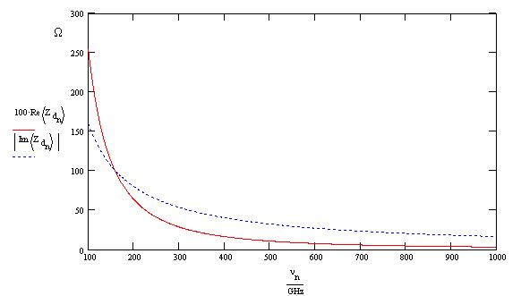
The real impedance has been multiplied by a factor 100. Using this evaluation for the impedance values and assuming that the antenna has a real impedance of 74 W we found the following results for the diode-antenna coupling.
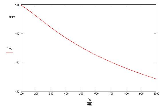
This represents the power delivered by the antenna to free space assuming that the diode is driven with a current of 100 mA.
3.2.4.5 Antenna-Receiver matching
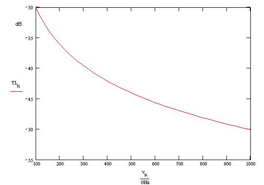
Let us consider now the efficiency of the coupling between the small antenna and the horn of the receiver. During the operation of the telescope several feed-horns will be changed to match the different frequencies so that the subreflector will always be fully illuminated, we can assume the beam pattern to be a gaussian with -11 dB point at the edge of the subreflector (3.58 deg6).
Also assume that the beam pattern of the planar antenna is a gaussian with -3 dB point at 20 deg7. As we saw we can increase the directivity by shaping the dielectric substrate.
Using these parameters we can evaluate the transmission loss of the antenna-receiver system and obtain the following result
Now if we consider the result achieved in the previous paragraph we can say that the total power available at the receiver is
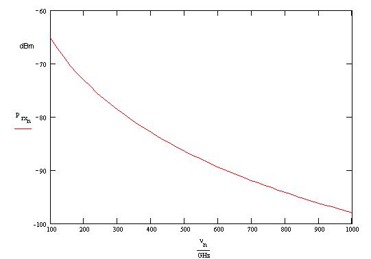
The minimum power is -105.6 dBm and this result shows that with this configuration we can satisfy the power request in the whole spectral range of interest..
3.2.4.7 References
[1] Victor H. Rumsey, Frequency Independent Antennas, Academic Press
[2] D. Chouvaev et al. - "Normal Metal Hot-Electron Microbolometer with Andreev Mirrors for THz Space Applications" - Ninth International Symposium on Space Terahertz Technology
[3] E.N. Grossman - "Lithographic Antennas fo Submillimiter and Infrared Frequencies" - IEEE Int. Symp. on Electromag. Compat. - 14-18 Aug. 1995, pp. 102-107
[4] Warren L. Stutzman, Gary A. Thiele - "Antenna Theory and Design" - Wiley & Sons
[5] G.V. Elftheriades et al - "A 20 dB Quasi-integrated Horn Antenna" - IEEE Micro. and Guided Wave Lett., Vol. 2, pp. 73-75 (1992)
[6] MMA Memo 246: James W. Lamb - "Optimized Optical Layout for MMA 12-m Antennas"
[7] M.A.
Tarasov et al. - "Quasioptical Josephson direct detectors for
mm-wave spectrum analysis" - Proc. of the Int. Conf. on mm- and
submm-waves and Applications (SPIE), 10-12 Jan. 1994, pp.
220-228
3.2.5 Combined Calibration System
The incoherent calibration scheme
described earlier switches between blackbody radiators of
different temperatures using a mirror. In principle, by allowing
an extra position on this mirror, the radiated calibration
signal can be switched between the incoherent blackbody loads
and the coherent radiator. At a later stage in the development,
when the feasibility of both coherent and incoherent calibration
schemes has been demonstrated, the combination of the different
calibration radiators into one packa ge will receive attention,
as will studies of how to achieve the necessary amplitude and
phase stability.
3.2.6 Work to be
done
The photonic calibration builds on work already in progress in the context of the photonic local oscillator scheme, with the exception of the broadband antenna. Some simple design work is required now (e.g. exactly how much coherent power needs to be radiated from the subreflector, with what requirements on amplitude and phase stability?) but the bulk of the effort can be expected fairly late in the ALMA development phase.
Reference:
D.
Bock, J. Welch, M. Flemming and D. Thornton, MMA
Memo 225: "Radiometer Calibration at the Cassegrain Secondary
Mirror." (See also the Appendix below.)
APPENDIX
The following figures are from the MMA
Memo 225 by Bock, Welch, Fleming and Thornton,
"Radiometer Calibration at the Cassegrain Secondary
Mirror."
Figure 1 shows the general Cassegrain optics, which normally has a scattering cone covering the central part of the subreflector to direct unwanted rays on to cold sky. Figure 2 shows a scattering mirror behind the subreflector, giving mu ch the same effect.
Figure 3 shows the absorbing black body load that would be placed behind the central hole of the subreflector
Figure 4 shows the arrangement of a rotating 45-degree mirror which will choose between one of two hot loads, whose temperatures differ by ~100 K, and the scattering cone from which rays which eventually reach cold sky.