The ALMA radiotelescope is currently planned to consist of a goal of
64 antennas, each of 12 m diameter. In this chapter we outline the
general requirements for the antennas and the detailed specifications can
be found in the contract for the US prototype antenna ( NRAO,
2000 ) and in the US Interface Control Documents (ICD) (ICD,
2000) which are part of the contract. The specifications and
ICDs for the European prototype antenna can be found on the ALMA-Europe
Antenna WWW Page. The principal requirements for the antennas are shown
in Table 4.1.
| Configuration | Elevation-over-azimuth mount, Cassegrain focus |
| Frequency range | 30 GHz to 950 GHz |
| Precision performance conditions | Nightime: wind 9 m/s Daytime: wind 6 m/s and sun from any angle |
| Reflector surface accuracy | 20 microns rms, goal; 25 microns rms, spec |
| Pointing accuracy, rms | 0.6 arcsec (offset, 2 deg in position and 15 min time), 2.0 arcsec (absolute) |
| Fast switching (settle to 3 arcsec pointing) | Move 1.5 deg in position in 1.5 seconds |
| Phase stability | 15 microns rms |
| Close packing | 1.25 dish diameters (15.0 m) between azimuth axis |
| Solar observing | Allowed |
| Transportability | Transportable on a rubber-tired vehicle |
The antennas will be designed and built by one or more commercial companies. Prototype antennas are being built for the US and European ALMA partners by Vertex Antenna Systems LLC (Santa Clara, CA) and European Industrial Engineering (EIE) (Mestre, Italy) respectively.
4.1. Introduction
The "antenna" subsystem of ALMA is here defined to include the following equipment:
12 m diameter primary reflector including quadripod subreflector support
legs.
Secondary reflector and its servo-controlled positioning platform,
including nutation.
A receiver cabin and its HVAC system.
Alt/az mount, the drive systems on the mount and the servo-system controller
for the drives.
Metrology instrumentation such as temperature probes, tiltmeters, laser
metrology systems, etc.
Power distribution cabling on the antenna and the cable wraps for these
cables.
Platforms for mounting auxiliary equipment such as cryogenic compressors.
Antenna foundation design but not fabrication.
Antenna transporter vehicle.
The detailed specifications for all of this equipment, except for the
Antenna transporter, can be found in the contract for the prototype antenna
(NRAO,
2000) and in the ICD's (ICD,
2000). A summary of the requirements, including the antenna transporter,
is provided below.
4.2. Specifications and Requirements
4.2.1 Operating Environment
The following operating environment defines the environment on the ALMA site in Chile. The first two prototype antennas will be tested at the VLA site in New Mexico (altitude 2100 m). It is likely that all production antennas will be assembled and undergo preliminary testing at San Pedro de Atacama (altitude 2440 m). Survival conditions at these test sites are no worse than the survival conditions on the ALMA site, except for the temperature maximum which has been selected as adequate for the test sites.
4.2.1.1 Location: Northern Chile, latitude -23d01m S, longitude 67d45m W.
4.2.1.2 Altitude: 5000 m (16400 ft) The barometric pressure at this altitude is 55% of its sea-level value.
4.2.1.3 Maximum Wind Velocity: The antenna must survive 65 m/sec (145 mph) without damage when positioned in its stow position.
4.2.1.4 Temperature: The antenna must operate correctly in the temperature range -20 C to 20 C. It must survive without damage the range -30 C to 40 C. The annual average temperature on the site is -4 C.
4.2.1.5 Precipitation: Annual precipitation on the site is in the range 10 cm to 30 cm per year. Most of this falls as snow but thunderstorms do occur and so brief periods of heavy rain and hail are possible. The antenna must be designed to survive, without damage, the following conditions: maximum rate of rainfall 5 cm/hr, hailstones 2 cm diameter at 25 m/s, snow load 100 kg/sq.m on reflector surface, radial ice on all exposed surfaces 1 cm. Surface heating to prevent snow and ice buildup not required.
4.2.1.6 Humidity: The monthly average humidity in the summer (January) is 53% and in the winter (June) it is 31%. The annual average is 39%. The monthly average water vapor pressure in the summer (January) is 4.0 hPa ( 4 gm/sq.cm) and in the winter (July) it is 1.2 hPa. The annual average is 2.3 hPa.
4.2.1.7 Insolation: The site location on the southern tropic, the high altitude and low water vapor result in insolation rates amongst the highest in the world. The median midday solar flux in the wavelength range 0.3-60 micrometers for the months of December and June are 1290 w/sq.m and 840 w/sq.m respectively. Ultraviolet radiation will be approximately 70% higher than at sea-level.
4.2.1.8 Lightning. Thunderstorms occur on the site so the antenna must be equipped with a lightning protection system.
4.2.1.9 Dust and Grit. The site ground surface is volcanic soil and gravel with no vegetation of any kind to stabilize the surface. It is likely that wind-blown dust and grit will be a factor for machinery operating on the site but this problem has not yet been well quantified.
4.2.1.10 Earthquake. The ALMA site is in a seismically active zone, but the source of the earthquakes, the tectonic plate interface, is more than 100 km below the surface so that the strength of the earthquakes is lower than the strength experienced closer to the Chilean coast. Design for 0.3G horizontal or 0.3G vertical acceleration.
4.2.2 General Configuration
The antenna will be a symmetric paraboloidal reflector, of diameter 12 m, mounted on an elevation over azimuth mount. Subreflector support legs will be a quadripod configuration. A reflector surface consisting of machined aluminum panels, or a panel technology providing equivalent accuracy, will be used. The reflector surface will be mounted on a carbon fiber reinforced plastic (CFRP) reflector backup structure (BUS). The BUS could be built completely of CFRP or could consist of CFRP structures connected by metal connectors. The quadripod will be made of CFRP. The reflector surfaces of the antenna will not be painted.
All drawings will have metric dimensions. All fasteners will be metric. The use of standard metric cross-sections for construction materials is preferred but will not be required if it results in a cost increase.
The antenna will be designed for a lifetime of 30 years. For design purposes it will be assumed that the antenna will execute not less than 270,000 complete cycles of elevation motion, where a complete cycle of elevation motion is defined to be movement of the reflector from its lower elevation limit up to its upper elevation limit and back down to its lower elevation limit. During its lifetime the antenna will execute not less than 200,000,000 degrees of total motion about each axis.
The supply voltage for the antenna will be the European standards, 230 v (single phase), 400 v (3 phase). All electrical systems must operate correctly on both a 50 Hz or a 60 Hz supply.
The antenna will be designed so as to conform to all relevant Occupational Safety and Health Administration (OSHA) or European safety codes.
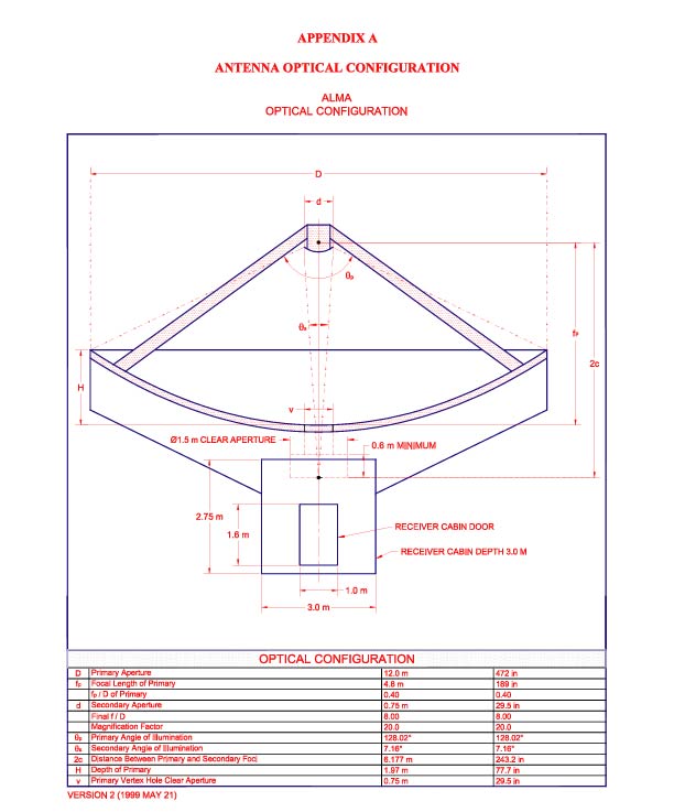
4.2.3 Reflector Geometry
The receivers will be located at the secondary focus of the Cassegrain geometry shown in Figure 1 (taken from Lamb,1999).
Figure 1. Optics Layout for ALMA Antenna
4.2.4 Range of Motion
Antenna foundations will be constructed so that the azimuth axis of an antenna is parallel to local gravity at the pad. For observations close to the zenith this will result in a difference in parallactic angle between antennas.
Minimum elevation angle for observations: 2 deg
Maximum elevation angle for observations: 125 deg. Cone of avoidance at the zenith: 0.2 deg in radius for normal sidereal tracking. Because of the high velocities and accelerations required for fast switching or on-the-fly mapping (see section 4.2.8 below) there will be a region around the zenith about 30 deg in radius, where azimuth switching times are degraded .
Stow position for wind survival: elevation 15 deg (this position was chosen so that, during a winter storm, the reflector can be oriented with its back into the wind to prevent build up of snow and ice in the dish. Stow position for maintenance: zenith (this position was chosen to prevent an antenna undergoing maintenance from mechanically interfering with an adjacent antenna in the most compact array).
Range of azimuth motion: 270 degrees either side of due north.
4.2.5 Reflector Surface Accuracy
The surface accuracy goal is 20 microns and the hard specification is 25 micrometers rms, including the subreflector contributions. The 20 micron and 25 micron surfaces will provide antenna surface efficiencies at 300GHz /900 Ghz of 94%/57% and 91%/41% respectively. At night this accuracy is to be achieved in a wind of 9 m/s which is approximately the 90th percentile wind for nighttime (2000 hrs to 0800 hrs) observing. During the day this accuracy is to be achieved for any orientation of solar illumination in a wind of 6 m/s. During the day the focus can be calibrated astronomically every 30 min.
The final, precision measurement of the surface will be done by the ALMA Project using holography. For the prototype antenna the contractor will provide a surface setting accuracy of 100 microns.The panel adjusters will be calibrated so that an adjustment point can be moved with a resolution of 5 micrometers. A full surface adjustment must require no more than 16 person-hours of work.
4.2.6 Pointing Accuracy
A pointing accuracy in "offset" pointing mode (calibrator 2 deg away every 15 minutes of time) of 1/30th primary beamwidth rms at 300 GHz is required. The antenna specification is 0.6 arcsec RSS for offset pointing, 2.0 arcsec RSS for absolute pointing. At night this accuracy is to be achieved in a wind of 9.0 m/s which is the 90th percentile wind for nighttime (2000 hrs to 0800 hrs) observing. During the day this accuracy is to be achieved for any orientation of solar illumination in a wind of 6 m/s.
4.2.7 Metrology
Provision will be made in the antenna design for inclusion of metrology equipment which will allow antenna pointing to be corrected for structural deformation caused by wind or thermal loading. Metrology systems for possible incorporation into the antenna include: a laser/quadrant-detector system to measure quadripod movement, tiltmeters, temperature probes and laser/retroreflector systems. The antenna contractor will provide any metrology that he considers essential for meeting performance specifications. An optical telescope with CCD camera for pointing on stars will be supplied by the ALMA Project.
4.2.8 Fast Motion Capability
Three observing modes require the ALMA antenna to have special fast motion capabilities: fast switching phase calibration, on-the-fly total power mapping and on-the-fly interferometric mosaicking.
Fast switching: The antenna will move 1.5 degrees on the sky and settle to within 3 arcsec peak pointing error, all in 1.5 seconds of time. The switching acceleration profile will be carefully designed so as to avoid exciting the lowest structural resonant frequency of the antenna. The maximum velocity and acceleration required for fast switching are 3 deg/sec and 12 deg/sec/sec on the sky respectively, with both axes able to move at this rate simultaneously. It is expected that this velocity and acceleration will be achievable in azimuth only for zenith angles greater than 30 deg (this implies maximum azimuth velocity and acceleration of 6 deg/sec and 24 deg/sec/sec respectively).
Analysis of the expected use of this fast switching mode (Holdaway, 1997) indicates that the antenna should be designed to survive 30-50 million cycles of fast switching during an assumed 30 year life.
On-the-fly mapping: In this mode the antenna will scan at a rate of up to 0.5 deg/sec across a large object, several or many beamwidths in size, and then turn around as rapidly as possible and scan back across the source in the opposite direction. A maximum acceleration of 12 deg/sec/sec is required for the turn around. While the antenna is scanning across the source the antenna position must be recorded at a rate sufficient to provide an angular sampling interval on the sky of wavelength/(2D) radians. For 0.5 deg/sec motion and 900 GHz observations this requires antenna position readout every 2 msec. The antenna positions should be accurate to 1 arcsec. As the antenna tracks across the source it is not necessary for the position at any time to be precisely a precommanded position; it is sufficient to simply know where the antenna is actually pointing and all antennas need not point precisely at the same position.
On-the-fly interferometric mosaicking requires interferometry data to be taken while the antenna is continuously scanning across the source. It is expected that the antenna velocity will be only one-tenth of its mapping-on-the fly value (see previous paragraph), but in this case all antennas must point to the same position at the same time to within 1 arcsec rms.
4.2.9 Subreflector Position Control
The subreflector will be supported on a platform which allows movement in all 3 linear directions. The precision of the mechanism will be adequate to allow the subreflector to be positioned, under computer command, with sufficient accuracy to prevent gain loss of more than 1% at 900 Ghz due to focus, comatic or astigmatic aberration. Position will be correctable on timescales of seconds. Total axial focus motion is 2.0 cm.
In addition to the above listed linear motions the prototype antennas will also be equipped with a subreflector nutator with the following specifications: 10 ms transition time, 10 Hz repetition rate, +- 1.5' throw, full dynamic balance. The decision as to whether all antennas will be equipped with nutators will be made after testing the prototype antennas.
4.2.10 Phase Stability
Phase errors caused by variations in the propagation pathlength through the antenna can be rapidly or slowly varying. Fast phase changes are primarily caused by the wind and the peak pathlength variation in a 9.0 m/s wind must be no more than 15 microns. Slow phase changes are primarily due to variations in the temperature of the antenna and the goal is to keep these phase errors small enough so that the residual errors after an astronomical phase calibration every 3 min are small enough to allow observations at 900 Ghz.
4.2.11 Close Packing
In the smallest array the antennas must be placed close together. It will be possible to place the antennas with their azimuth axis within 15 m (1.25 D) of each other without any possibility of the antennas hitting each other, no matter what the relative orientation of the two antennas.
4.2.12 Solar Observing
Direct observations of the sun will be allowed. All surface accuracy and pointing requirements must be met while observing the sun and a suitable surface treatment of the primary reflector surface must be provided to prevent solar heating damage of the subreflector or its support legs. When observing the sun the solar heating of the secondary focal plane must be less than 0.3 W/sq.cm.
4.2.13 Low Antenna Noise
Contributions to system noise from the antenna, due to such mechanisms as scattering of ground noise into the feed and resistive loss of reflector surfaces, will be minimized as much as possible without compromising the surface accuracy and pointing requirements. Design features to be considered to achieve this goal include supporting the subreflector support legs close to the edge of the reflector and shaping the underside of the support legs to reduce ground pickup. Geometrical blockage will not exceed 3.0% and resistive loss of any reflective surface will not exceed 1.0% at frequencies up to 950 GHz.
4.2.14 Transportability
To move the antennas from one array configuration to another the antennas will be picked up and carried on a transporter vehicle which runs on a gravel road on rubber tires. The transporter with an antenna on board will be able to negotiate a 15 % grade, turn a corner with a minimum turning radius of 10 m and travel at 10 km/hr on the flat and 5 km/hr up a 10% grade. An unloaded transporter must be able to travel at 20 km/hr on the flat. The transporter must be able to safely move an antenna in winds up to 16 m/s (this is approximately the 95th percentile for the winds on the site at 1600 hrs local time, the time at which the winds are maximum each day). A stationary transporter with an antenna on board will survive winds up to 65 m/s; if necessary, structure can be deployed to stabilize the transporter on the ground in this survival mode. To withstand the bumps and jolts of transportation and pickup/putdown the antenna will be designed to survive shock loads of 4 G vertical and 2 G horizontal acceleration.
The transporter will carry an auxiliary generator to keep all electrical systems on the antenna operational during a move. The transporter will pick up the antenna above its azimuth bearing so that the azimuth bearing and drive can be used to rotate the base of the antenna to simplify bolt hole alignment when an antenna is placed on a pad. It may be desirable to oxygenate the air in the transporter operator's cabin so the cabin must not have large air leaks.
When an antenna is picked up a time goal of 20 min is required from the time of arrival of the transporter to the time of departure with an antenna on board. When an antenna is placed down on a pad a time goal of 30 min is required from the time of arrival of the transporter until the transporter has departed and the antenna is ready to be pointed.
A current design concept for the transporter can be found in ICD NO.
5 ANTENNA/TRANSPORTER INTERFACE available at ICD,
2000
for the US antenna and ALMA-Europe
Antenna WWW Page for the European antenna. Because of differences in
the antenna design, the US antenna has 4 transporter attachment points
and the European antenna has 3. The current goal is to design the prototype
transporter so that it can pick up either antenna.
4.2.15 Receiver Cabin
A receiver cabin with dimensions approximately as shown in Figure 1 will be provided at the Cassegrain focus. Temperature in the equipment air supply plenum will be maintained by an antenna mounted HVAC system at a setpoint in the range 16-22 C to an accuracy of +- 1C. The electrical power consumption of equipment in the cabin will not be greater than 10 kw. The mass of equipment in the cabin will not be greater than 1600 kg.
A built-in mechanism will be provided so that a receiver can be lifted from the ground, through the cabin door and into its observing location, all without significant man-handling of the receiver. Part of the installation of a receiver may involve the use of a separate special purpose vehicle, such as a high fork-lift, which lifts the receiver through the cabin door.
The cabin will be watertight and a thin RF-transparent membrane will cover the aperture through which the RF beam enters the cabin. A computer actuated shutter will be deployable to protect the membrane when necessary.
It may be desirable to oxygenate the cabin air when workers are inside so the cabin must not have large air leaks.
A typical layout for the receiver cabin is shown in Figure 2.
Figure 2. Typical layout for ALMA receiver cabin.
4.2.16 Monitor and Control
Lists of monitor and control points for the antenna can be found
in
ICD NO. 9 ANTENNA/MONITOR AND CONTROL INTERFACE, available at (ICD,
2000) for the US antenna and at ALMA-Europe
Antenna WWW Page for the European antenna.
4.2.17 Interfaces to Other Subsystems
Interfaces to the various ALMA subsystems are defined in the ICDs available at (ICD, 2000) for the US antenna and at ALMA-Europe Antenna WWW Page for the European antenna.
ICD NO. 1 ANTENNA/RECEIVER INTERFACE
ICD NO. 2 ANTENNA/APEX INTERFACE
ICD NO. 3 ANTENNA/SITE ELECTRIC POWER INTERFACE
ICD NO. 4 ANTENNA SITE FOUNDATION INTERFACE
ICD NO. 5 ANTENNA/TRANSPORTER INTERFACE
ICD NO. 6 ANTENNA/CABLE WRAP INTERFACE
ICD NO. 7 ANTENNA/HELIUM COMPRESSOR INTERFACE
ICD NO. 8 ANTENNA/OPTICAL POINTING TELESCOPE INTERFACE
ICD NO. 9 ANTENNA/MONITOR AND CONTROL INTERFACE
ICD NO. 10 RECEIVER CABIN EQUIPMENT RACK INTERFACE
ICD NO. 11 BASIC ANTENNA DEFINITIONS
4.2.18 Maintenance and Reliability
Because of the remote site and large number of antennas the reliability and maintainability of the antennas are important. The antennas will be designed so that, with normal preventive maintenance, they should operate for 30 years without requiring elevation or azimuth bearing or reflector surface replacement. Although they should not be required, straightforward elevation and azimuth bearing replacement procedures must be included in the antenna design. All normal repair and maintenance actions should be able to be completed by a two- person crew in 4 hours. To the maximum extent possible all equipment on the antenna should be "modularized" so that a failure can be cured by simply swapping out the failed component without the need for any repair in place. Examples of equipment which should be designed for easy replacement includes gear boxes, drive motors, HVAC equipment, servo-system electronic components and the subreflector position control mechanism.
4.2.19 Manufacture and Assembly
The antenna will be designed for economic production costs.
The first two antennas will be tested initially at the VLA site in the US. At least one of the prototype antennas will later be shipped to the ALMA site so the ability to disassemble the antenna into pieces for overseas shipping is required.
The high altitude and remoteness of the ALMA site make it desirable to minimize the amount of work required on the high site. It is expected that the antennas will be assembled, outfitted and tested at an Operations Support Facility in San Pedro de Atacama 50 km from the ALMA site at an altitude of 2400 m. They will be carried to the ALMA site on the transporter vehicle or, in the event that this proves not to be feasible, they will be disassembled into just two pieces, the mount and the reflector, for transportation to the site on trucks. Thus the antenna will be designed for easy disassembly at the elevation axis and both the reflector and mount must have pickup points for handling as single units.
4.3. Design Concepts
Four antenna concepts were developed within the ALMA Project.
A 10 m concept developed principally at NRAO and BIMA( Lugten
et.al., 1999 )
A 10 m concept developed principally at OVRO( Woody
and Lamb, 1999 )
A 12 m concept developed principally at ESO ( Andersen,
1999 )
A 12 m concept developed principally at IRAM ( Plathner,
1999 )
These concepts were provided to the bidders during the proposal phases
for the NRAO and ESO contracts to assist the bidders in making their proposals..
Concept pictures of the antennas being designed by the two contractors are shown in Figures 3 and 4.
Figure 3. European Industrial Engineering antenna concept.
Figure 4. Vertex Antenna Systems antenna concept
4.4. Procurement and Construction Plans
The following is a list of the principal tasks, with date goals for the major milestones, required in the ALMA Project to progress from prototype antenna delivery to a contract for production antennas:
Installation of prototype antennas at VLA site - 4Q 2001
Contractor Acceptance Tests - 4Q2001
Tests
Evaluation
Selection of production design
Specification for Production Antennas (build to print) - 2Q 2003
Call for Tenders
Bidding
Selection
Approval
Contracting - 4Q 2003
4.5. References
T. Andersen, "Feasibility Study for a 12 m Submillimeter Antenna",
ALMA
Memo 253, Feb 1999.
M. Holdaway, "How many switching cycles will the MMA make in its lifetime", ALMA Memo 174, 1997.
Antenna Interface Control Documents, ALMA, NRAO, (ICD, 2000), Feb 2000.
J. Lamb, 1999, Optimized Optical Layout for MMA 12-m Antennas, ALMA Memo 246, Jan 1999.
J. Lutgen, J. Kingsley, J. Cheng, V. Gasho, M. Fleming, "A 10-m Antenna Design for the Millimeter Array", ALMA Memo 240, Feb 1999.
NRAO, ALMA US Prototype Antenna Purchase Order, February, 2000.
D. Plathner, "A 12m Telescope for the MMA-LSA Project", ALMA Memo 259, April 1999.
D.P. Woody, J.W. Lamb, "A Design for a Precision 10-m Sub-Millimeter
Antenna", ALMA
Memo 241, Mar 1999.