A. Orlowska, M. Harman, B. Ellison
Last changed 2001-Jan.-29
Revision History
2001-Jan.-29: First ALMA version
Contents:
6.2
Design Summary *6.3
Cryostat Design Requirements and Objectives *6.4
Detailed Cryostat Design *6.4.1
Outer vacuum container *6.4.2
Internal radiation shields (70 K and 12 K) *6.4.3
4 K heat sink stage *6.4.4
Cartridge design *6.5
Cryocooler selection *6.5.1
Cooler requirements *6.1.2
Heat loads *6.1.3
Number of stages *6.1.4
Cooler type *6.1.5
Temperature *6.1.6
Temperature stability *6.1.7
Cycle *6.1.8
Cryocooler selection summary *6.6
Production and construction *6.6.1
Issues *6.6.2
Proposed method of assembly *6.7
Performance summary *6.8
Compliance table *
List of Figures:
Figure 6-1: ALMA cryogenic system concept showing optics, cartridge and cryocooler arrangement
*Figure 6-2: Cut-away view of outer vacuum container (OVC)
*Figure 6-3: Bottom view of cryostat with cartridges extended
*Figure 6-4: Cross-sectional view of cryostat showing internal support bar
*Figure 6-5: Unsupported Vacuum vessel endplate deflection
*Figure 6-6: : Example of an ALMA receiver cartridge
*Figure 6-7: : Cartridge location on OVC endplate
*Figure 6-8: : Illustrates FE model of estimated cartridge deflections when cryostat axis is horizontal
*Figure 6-9: Illustration of cartridge support conductive heat flow
*Figure 6-10: Preliminary design of the ALMA cryostat thermal link arrangement
*Figure 6-11: : Estimated thermal link clamping forces when cold
*Figure 6-12: Distribution of thermal links on the 4K base plate A similar arrangement is used for the radiation shield links
*Figure 6-13: Modified thermal link arrangement
*Figure 6-14: Top view of cryostat showing signal input window layout
*
The ALMA cryogenic system performs a critical role within the array operational infrastructure by providing the necessary cooling for all low noise receiver front-ends associated with the instrument. It is vital for successful operation of the array that the cryogenic system provides appropriate thermal cooling capacity and stability, mechanical robustness and a high degree of reliability. Furthermore, the system design must offer a degree of flexibility for planned and future receiver technology development and yet be sufficiently simple to ensure minimum and straightforward construction and maintenance. Achieving these requirements is a demanding development task and one that requires the application of novel design and construction methods coupled with the selection of the most suitable cryogenic cooling engine.
This report provides a summary of the design progress to date and although preliminary in a number of aspects, for example thermal heat loads, mechanical deflections tolerances and dimensional constraints need to be refined, it represents the envisaged structure and design methodology.
The present preliminary design is able to accommodate ten receiver observational bands operating in the millimetre to submillimetre wavelength range. In addition, sufficient room has been allowed for inclusion of an atmospheric water vapour monitor (for either cooled or room temperature operation) and, should it be necessary, a receiver calibration cold load. The radio frequency and other electronic components that form an individual receiver band are integrated into an autonomous support structure known as a cartridge assembly. All ten cartridges are inserted into a single large vacuum vessel (see Figure 6-1) that provides thermal insulation, radiation shielding and cryogenic heat lift, the latter via a close cycle cooling system. Further, the outer vacuum container (OVC) supports external optical components associated with the receiver-antenna optical interface: internal optical components are supported on individual cartridge assemblies. Thermal connection to each cartridge assembly heat sink stage is provided via a novel low resistance thermally activated link arrangement that requires no permanent mechanical attachment, i.e. it does not need to be physically bolted to a stage. This mechanism provides a significant operational advantage in that withdrawal of a cartridge, and hence a complete receiver band, can be simply performed at room temperature and ambient atmospheric pressure without disturbing the rest of the receiver and cryogenic system. This minimises risk of damage to the remaining receiver bands, reduces maintenance time and avoids a potentially lengthy and difficult readjustment of the external optical assembly since this need not be separated from the vacuum vessel. Furthermore, adoption of the cartridge principle allows construction and test of individual receiver assemblies to be performed at separate development facilities prior to final integration into the main vacuum vessel. We believe that this approach will provide a significant advantage to the ALMA receiver development community and is consistent with the likely multinational distribution of receiver development tasks.
Figure -1: ALMA cryogenic system concept showing optics, cartridge and cryocooler arrangement
Individual elements of the cryogenic system conceptual design are described in greater detail within the following sections.
The basis of the cryostat design can be divided into a number of key requirements as shown below. Associated with each requirement heading are a series of design objectives that, when met though the design process, will ensure the construction and operation of a cryogenic system that is well suited for the ALMA instrument.
Detailed Cryostat Design
The ALMA cryostat must fulfil the cryogenic requirements of the front-end receiver technology and, in addition, must operate with high degree reliability, efficiency and be compliant with large-scale production. To ensure that the cryostat satisfies these objectives, it is essential that contributing factors that could limit the system performance or be a cause of reliability concern are identified and resolved.
Our design procedure has established the main criteria that affect both system performance and reliability to be associated with:
Alignment issues are predominantly associated with the ability of individual cartridges to remain co-aligned with the room temperature external optical assemblies as the cryostat is tipped on the telescope. Furthermore, the cartridge structure must be sufficiently rigid to resist distortion during receiver component integration, general handling and subsequent thermal cycling.
Provision of appropriate cooling capacity is dependent upon selection of the most appropriate cryocooler technology and careful evaluation of parasitic heat loads due to radiative, conductive and power dissipating sources. The cartridge structure provides a significant contribution to the conductive load and, as a result, its design is crucially important to successful cryostat operation.
The following sections describe of the major features of the cryostat design by splitting the whole cryogenic system into two main parts namely, the vessel structure, including OVC, radiation shields and cartridges, and the cryocooler. Detail and drawings are those available at the current time of issue of this report..
The conceptual design of the OVDC is shown in Figure 6-2. It essentially consists of a metal cylinder (mid-section) capped at both ends with metal plates that support the signal input windows at one end and the receiver cartridges at the other. With the exception of the cryocooler system, all porthole access ports (window, cartridges, vacuum vale and vacuum gauges) are placed on the surface of the two endplates.
Figure -2: Cut-away view of outer vacuum container (OVC)
The ‘top’ endplate has 12 portholes with a suitable ‘O’ ring seals that provide locations for the input signal windows, water vapour radiometer (signal input window if cooled or cold load window if warm) and, if required, a generic receiver cold load. The base of the vessel has 10 ‘O’ ring sealed interfaces for the cartridges and four additional ports for vacuum pump and vacuum gauge attachment, thermometry and heater electrical cabling feedthroughs. The envelope dimensions for the OVC are approximately ø1m x 0.7m high, and are consistent with the antenna cabin access door. Figure 6-3 shows the bottom end plate with the cartridges extended from the OVC.
Figure -3: Bottom view of cryostat with cartridges extended
The mid-section provides the radial support structure of the vessel and contains the suspension supports. It also provides ‘O’ ring sealed access for the attachment of the cryogenic cooler. A central internal tube has been introduced between the two end caps (see Figure 6-4) in order to reduce the endplate deflection when the system is evacuated. Figure 6-5 shows the extent to which a simple endplate structure (holes excluded) deforms without the addition of the tube. Additional metal ribbing is also included to reduce the residual deflection to < 0.1mm. It is anticipated that addition of the window and cartridge access holes will weaken the endplates, particularly at the cartridge end, and some additional mechanical stiffening may be required in order to achieve the required deflection. This is currently being investigated.
Figure -4: Cross-sectional view of cryostat showing internal support bar
Figure -5: Unsupported Vacuum vessel endplate deflection
The OVC construction material can be either stainless steel or aluminium and in both cases fabricated in accordance with a pressure vessel design code BS5500. The final material choice requires detailed structural analysis that is currently ongoing, and selection will most likely be a compromise between structural mass and rigidity rather than cost. Additional consideration must also be given to the ability of the chosen material to provide a low surface emissivity, low outgassing properties and ruggedness. This normally implies a preference for stainless steel, but the total cryostat mass restriction of < 750 kg means that material thickness must be minimised and resulting deformation carefully evaluated. We have also considered the use composite materials since they may provide a significant mass advantage. However, our concerns with regard to their suitability, they are not proven in this area and therefore introduce production and performance uncertainty with little cost benefit, lead us to reject their use at the present time..
Attachment to and accurate alignment between an antenna and cryostat is achieved by use of precision registers and dowel pins located at appropriate intervals on an interface ring. Our intention is that registration between an antenna and cryostat be non-specific. That is, individual cryostats can be interchanged between any of the array antennae and external optics assemblies. The will greatly ease assembly, test and maintenance requirements though, for a cryostat of the size conceived, will not be a trivial task. Final definition of cryostat – antenna interface alignment tolerance is currently awaiting outcome of analysis from the ALMA Optics Group.
The function of the cryostat internal radiation shields is to reduce the radiative thermal load on the 4 K stage. An addition function is to provide a good heat path between the thermal link arrangement and the cryocooler heat lift stages. The shields are constructed of pure aluminium (BS1470 grade 1200 or equivalent) and provide good thermal conduction properties, relatively low outgassing, low mass, ease of manufacture and low cost. In order to reduce the emissivity and outgassing rate further, a specialist surface treatment using chemical cleaning will be used to clean the surface. An acid etching technique, which has been proven in a production environment, is a cost-effective surface treatment method. Once clean, however, surfaces will be prone to contamination and it is therefore essential that careful procedures are employed, preferably in clean room environment, during assembly and maintenance.
A substantial load has been calculated to be incident upon the 70K shield from the room temperature OVC. Even though the cryocoolers specified in Section 6.5.0 provide a large heat lift capacity, this amount of radiation represents a significant load on the cooling system and may ultimately impact cooling effectiveness and reliability. A standard technique to reduce this load is to apply several layers of multi-layer insulation, often interleaved with polyamide netting to reduce thermal conduction, to intercept the radiative heat load. Although the use of multi-layer insulation will increase the evacuation time, our initial estimate of the reduction in radiative heat load onto the 70 K shield (typically to by 20 W) leads us to believe that its introduction is well worth while. A similar reasoning applied to 12 K shield indicates that a single layer of aluminium foil 0.08mm thick would be sufficient to reduce the radiative heat load from the 70 K shield to acceptable levels. The aluminium foil is a cost effective method of providing a surface with a very low emissivity without the use of more expensive polishing or plating processes.
The effectiveness of the radiation shields is also a function of how they are supported. For example, it is essential that the support structure implemented does not introduce an excessive thermal conduction path since this would raise the temperature of the shield either throughout or in local areas. However, it is also essential that any support structure be sufficiently rigid to prevent excessive displacement of the shield as the cryostat is tipped on the telescope. Although the shield structure is connected to the cartridge via highly flexible links (see Section 6.4.4.3), alignment must still be maintained within ±0.5 mm in order avoid to the introduction of additional cartridge deflection. Clearly, achieving tolerance of this order require the minimisation of the shield mass.
The 4K plate construction is of machined OHFC copper plate. OHFC copper has been selected primarily due to its properties as a good thermal conductor at 4K but also because of its low outgassing properties, ease of manufacture, availability and cost. The grade selected will be to BS2870 grade C103/110 or equivalent. The plate will have features for attachment of thermal links, low conductivity supports, and suitable cooling engine connections. The overall shape must be optimised in order to provide adequate thermal conductance at 4K. Consideration also needs to be give to the mass of the plate and this should be minimised in order to provide increased cooldown efficiency.
Adoption of a receiver cartridge philosophy provides the following benefits:
Maintaining the optical alignment between observing band components and external optical units during transportation cool down, and operation is of a fundamental importance to the proper operation of the receiver system. All radio frequency (RF) optical components have a requirement to be mounted on mechanically stable structures. The mechanical loads have been identified which could adversely affect optical alignment are deflections of the vacuum vessel after evacuation, thermal contraction during cool-down, tilting of the antenna, transportation of the receiver and the interchange of production receiver components during maintenance, or complete front-end replacement.
The cryogenic system is capable of support a total of 10 individual cartridges. Each cartridge contains all the necessary components, ancillary electronics and cabling associated with a specific front-end band. There are 8 cartridges with an outside diameter of 170mm and 2 cartridges with an outside diameter of 140mm. Ideally, cartridges would be identical in shape, but space limitation within the OVC has prevented this. In Figure 6-6 we show a example of a typical cartridge structure and in Figure 6-7 the corresponding cartridge location on the OVC endplate.
Figure -6: : Example of an ALMA receiver cartridge
Figure -7: : Cartridge location on OVC endplate
The structural form of a cartridge comprises a room temperature base plate, that mates with the OVC, to which is attached a series of thermal insulators that separate three cold surfaces, referred to as the 70K, 12K and 4K stages. In the case of receiver bands 1 and 2, a 4K surface in not required and can be simply omitted from the cartridge assembly during construction. All necessary electrical connection and feedthroughs are located on the room temperature base plate making each cartridge and autonomous assembly. The thermal isolation between cold stages is accomplished by use of thin walled fibre glass tubing that has been optimised for thermal resistance and mechanical rigidity. Figure 6-8 indicates a preliminary finite element (FE) analysis of the cartridge structure: the smaller diameter indicates the distribution of the 4K end load (mirrors, mixers etc.) and increasingly blue area indicates the region of greatest deflection. Figure 6-9 indicates the corresponding conductive heat flow through the corresponding tube structure.
Figure -8: : Illustrates FE model of estimated cartridge deflections when cryostat axis is horizontal
Figure -9: Illustration of cartridge support conductive heat flow
The concept of the cartridge assembly is very similar to that employed in hybrid helium dewars used at a number of observatories for millimetre and submillimetre wave system. Further, it benefits from the heritage gained of a similar, though smaller system, successfully developed and employed by NRAO on the 12m Kitt Peak antenna. However, the current design differs from past systems in one important aspect namely, the thermal anchor or link arrangement. In this case, a novel mechanism is proposed in which connection between a cartridge cold stage and the cryocooler heat sink point is achieved via a temperature dependent thermal link.
An early version of the link, which has undergone preliminary tests, is shown in Figure 6-10. The basic mode of operation involves the thermal contraction of a nylon and copper ring assembly surrounding a specific cartridge cold stage, as the cryostat temperature is reduced. The cartridge assembly passes through the ring, which is a relatively loose fit, and is self-aligned with the appropriate cartridge temperature stage. On system cool down, the nylon ring contracts at a greater rate than its metal counterpart and, as a result, squeezes the metal ring into contact with the cartridge and thereby forms a thermal link. Tolerance between the link inside diameter and stage outside diameter are selected such that when cooled operation is achieved a substantial force is exerted between the surfaces and a low thermal resistance joint is formed. An estimate of the clamping force produced by this arrangement is shown in Figure 6-11: a clamping force in excess of that obtainable from a conventional bolt arrangement is predicted. A series of radial flexible braids attach the link to the cryocooler cold plate and allow free mechanical movement of the link. This is necessary to avoid distortion of the cartridge during cooldown and any deflections that may arise from movement of the radiation shields during use on a telescope. The clear advantage of this system is that it provides minimum mechanical intervention to insert or remove a cartridge assembly since when the cryostat is a room temperature, the link compression is relaxed and becomes free of the cartridge stage. In addition, the system also allows cartridges to be placed closer together and results in a more compact cryostat envelope.
Figure -10: Preliminary design of the ALMA cryostat thermal link arrangement
Figure -11: : Estimated thermal link clamping forces when cold
A thermal link similar to that shown in Figure 6-10, but reduced in scale, has been manufactured and tested. Measurements indicate successful operation and repeatable performance: the link was thermally cycled 10 times between sets of measurements with no apparent degradation in function. Table 1 shows the measured thermal gradient across the link which, although limited by the test arrangement, appear to be acceptable at 12 K and 70 K. The conductivity at 4 K needs to be improved if heat loads higher than 30 mw are anticipated. A full report on the tests is available Improvements to the design have been made, reducing the number of interfaces, and a new link will be tested.
Table 1: Thermal conductance and temperature gradients at different heat loads and stage temperatures
|
Temp (K) |
K (W/K) |
Load (mW) |
ΔT (K) |
|
4 |
0.12 |
40 |
0.33 |
|
100 |
0.83 |
||
|
12 |
0.74 |
40 |
0.05 |
|
100 |
0.14 |
||
|
80 |
1.3 |
40 |
0.03 |
|
100 |
0.08 |
Achieving adequate thermal conductivity of the links at 4K is crucial. The temperature distribution across the link must be maintained to ~ 0.2K to avoid degradation of the superconducting mixer performance. This reduces the link material selection for the link to high purity metals, e.g., aluminium or copper. Since flexible copper links are readily available commercially it was felt that their use would provide the most cost-effective selection for the flexures. Furthermore, good connection of the link to the radiation shield base is essential is cartridge stages are to be properly cooled. Because of the large number of links that are required on each stage, space is at a premium and must be therefore used very efficiently. An arrangement shown in Figure 6-12 is proposed for link distribution on the radiation shield (and 4K stage) plates.
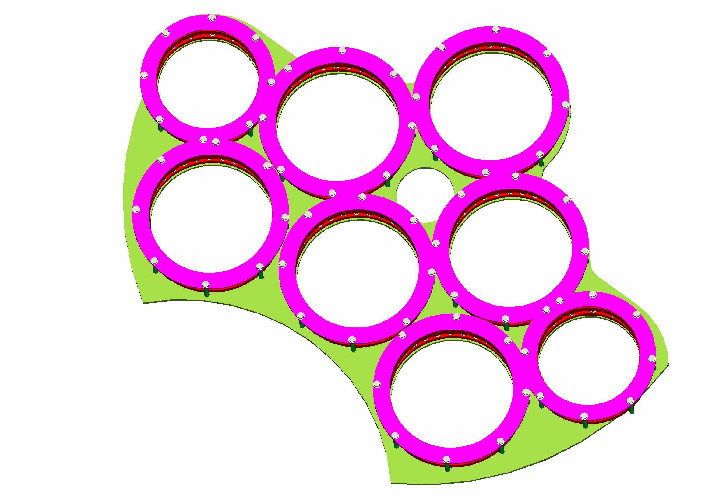
Figure -12: Distribution of thermal links on the 4K base plate A similar arrangement is used for the radiation shield links
Due to the number of thermal link assemblies required (provisionally 28 per cryostat) the links must be compliant with existing commercial production techniques and large-scale manufacture. For example, all components in the link assembly should be capable of manufacture using conventional milling, turning, brazing processes or laser/water cutting techniques. Several flexible thermal braids have been considered. The structure selected is provided by a local expert cryogenic company (Oxford Instruments) and has a great deal of production and cryogenic heritage (approx. 250,000 in service). Estimated cost per braid is approximately $1.5 each. It is proposed that a vacuum brazing technique be employed for attachments of the braids into a copper clamping ring. Although vacuum brazing is a relatively expensive process for 1 off production due to the high cost of heating the oven, for volume production there are significant cost savings. The flexible braid has a crimped end that eliminates the wicking effect of the solder that will occur during brazing or soldering. An additional benefit of brazing is that no expensive post manufacture cleaning is required; conventional soldering generates large oxide layers which require cleaning which can often be a lengthy and unsatisfactory process and can leave residual outgassing components.
The utilisation of laser/water cutting is proposed for the production thermal links where precision machining is not a requirement on non-critical surfaces and can achieve tolerances to approx. 0.3mm. Laser/water cutting is a cost-effective process for cutting profiles in volume component production since it is automated, quick and with a minimal amount of set-up time. It is becoming common place in most metal stockholder or machine shops.
An updated design for the thermal link arrangement is shown in Figure 6-13. We intend, through collaboration with the NRAO, to manufacture and test this new version prior to the cryostat production phase. The new design is of a larger link, suitable for all the 170
φ cartridges and has eliminated one bolted joint per braid. This should lead to an increase in conductivity.
4 K link 12 and 70 K link
Figure -13: Modified thermal link arrangement
As previously indicated, the cartridge is composed of 3 main sub-assembly sections (77K, 12K and 4K stages), vacuum plate, and thermal isolation support structure. The vacuum plate will be manufactured from stainless steel. Associated waveguides and electrical interfaces will be required to be integrated onto the base of the vacuum plate and stainless steel is the most suitable material for this. The grade selected will be to BS1501 grade 304S12 or equivalent. This grade has been selected for its high strength, machine and weld ability, corrosive resistance, cost effectiveness, and availability. The cold plates will be manufactured from pure aluminium The grade selected will be to BS1470 grade 1200 or equivalent as for reasons previously stated. The cold plates can be modified to suit individual RF band design configurations and if required additional fixing holes and cut-outs may be added. An appropriate surface finish will be required around the periphery of the cold plates to ensure the thermal link assemblies can make good thermal contact thereby minimising joint thermal resistance. The cold plate support structure will be manufactured from GRP (Glass re-enforced plastic). The tubes will be slotted to increase the thermal path and the slots optimised utilising finite element analysis techniques to provide a suitable trade off between rigidity and thermal resistance. It will be important to control the manufacturing process and quality of the tubes since orientation of the glass fibres and resin epoxy significantly affects the thermal and mechanical qualities of the composite material. In addition, construction and assembly of the whole cartridge will need to be carefully specified and monitored since specific tolerances must be achieved in order to ensure proper function of the thermal link and adequate alignment and interchange of the assemblies.
Cooling the SIS mixers to ≤ 4.0 K and achieving appropriate temperature stability is a critical objective if optimum receiver performance if to be attained and maintained and is a function of the overall system efficiency. In order to achieve good cooling efficiency we must first identify all sources of significant heat input. With the ALMA cryostat the areas that contribute to the system thermal loading are:
An additional radiative heat source is from the signal input windows (see Figure 6-14). This heat load will be intercepted at the different heat stages utilising a method of infrared (IR) radiation filtering. Each IR filter corresponds to a signal observing band and will be optimised to ensure that it does not compromise receiver system sensitivity and hence observing performance. At present the IR filters designs for the ALMA IR filters are unavailable and thus, only budgetary estimates based on the past experience of receiver development groups are utilised.
Figure -14: Top view of cryostat showing signal input window layout
The prime design driver for the support structure is to ensure that RF optical alignment is maintained but as for the reasons stated earlier it is beneficial to minimise the heat leak transfer onto the cold stages. Due to the conflicting nature of these requirements optimisation of the supports will be required and a suitable trade off between rigidity and thermal conductivity made. A more detailed analysis will be conducted using finite analysis techniques that give high degree of accuracy in predicting both mechanical stability and thermal conductivity and so providing a high level of optimisation
In addition to satisfying the cooling requirements for ALMA, selection of the cooler must include the additional following considerations:
The cryostat thermal models are preliminary and further analysis is underway in respect of some parameters such as filtering, mechanical supports, local oscillator dissipation etc., are indicated in Table 2 (all TBC).
Table 2: Estimated maximum cryocooler heat lift requirement
|
Temp. Stage |
Loading |
Total Stage Load (Max.) |
Comment |
|
70K |
26 W + support + LO +IR loads + margin |
40 W |
Plus extra if JT used |
|
12K |
5 W + support + margin |
8-10 W |
Plus extra if JT used |
|
4K |
0.6 W + support + uncertainty in IR loads |
0.75 - 1 W |
Cooling required at T ≤ 3.8 K |
Depending upon the type of cooler selected, two configurations can be considered, (each with several possible means of realisation)
The cryostat will be large with extended surface areas incurring large radiative loads. Many decisions, yet to be confirmed, will affect the thermal loads (number/size of windows, use of Multi Layer Insulation, optical design etc) and a margin on cooler performance will be required. It is much more thermodynamically economical to intercept heat loads at about 70 K where cooling is relatively cheap, rather than at a lower temperatures. Although input power is not the primary consideration in selection, the problems of heat dissipation at high altitudes have to be borne in mind. For these reasons the 3 stage system is preferred.
A 3 stage system could either be implemented by one cooler type, e.g. a three stage Gifford-McMahon (GM) or pulse tube, or by a two stage cooler with the coldest stage provided by a further stage of a different type, e.g. a two stage pre-cooler with a helium JT stage. Both systems have some advantages; simplicity and ease of integration in the case of a single cooler, distributed cooling and efficiency in the case of the JT option.
Both GM and pulse tube coolers operating at low frequencies suffer considerable loss of cooling when run in orientations more than about 30 degrees from optimum (cold finger pointed down). This is a problem at all temperatures but more significant at 4 K. GM coolers lose about 10% of their cooling power when horizontal, pulse tubes probably more.
A maximum temperature of 4 K at the receivers is a requirement. Some margin in the temperature is necessary in order to provide for heat transfer at the receivers and hence sub 4 K operation is required at the cryocooler cold finger. To achieve a temperature of 3.8 K, however, a JT system would require an exhaust pressure of less than 0.657 bar, lower temperatures require lower pressures, but the temperature remains constant with heat lift (until the maximum heat lift is reached). This is a challenging requirement.
A GM or pulse tube cooler would have a base temperature below 4 K, but the temperature would be dependent on heat lift, and possibly orientation. Currently available two stage GM coolers have base temperatures below 3 K.
Heat transfer at 4 K is an important issue. A JT stage offers distributed cooling with potentially shorter conduction paths to the receiver channels. This advantage must be weighed against the additional complexity of the cold plumbing. A 4 K or GM cooler gives single point cooling and heat must be conducted from each of the channels. For a large system this is disadvantageous but such methods have been used successfully on smaller systems.
Temperature stability requirements at 4 K are extremely stringent, around 2 mK peak to peak over one minute (TBC). The temperature of both GM and pulse tube coolers is orientation dependent so such coolers would be used with their axis parallel to the elevation axis.
Temperature stability of JT systems is good, as the temperature only depends on the exhaust pressure at the orifice. To achieve similar stability with a 3 stage cooler high heat capacity such as a rare earth (or a helium reservoir) would have to be introduced at the 4 K plate.
Both GM and pulse tubes can be considered. The GM cooler is well established commercially with a number or manufacturers and known reliability. Such coolers are produced in very large numbers for the MRI and cryopumping markets. Service intervals of about 10,000 hours for the expander and 20,000 hours for the compressors are quoted although anecdotal evidence points to longer life. The main source of wear problems is the sealing of the displacer unit and the valves. Vibration levels are relatively high, but such coolers have been used successfully on telescopes and in the laboratory. The vibration levels of mechanically driven expanders are significantly lower than those generated by pneumatically driven systems.
Pulse tubes are becoming established commercially although fewer manufacturers are involved. The compressor units used are the same as those for GM coolers and will have the same service intervals. The pulse tube itself has no moving parts and the valves cans be mounted at a slight distance (say 30cm) from the cold unit, simplifying servicing and greatly reducing any vibration in the cryostat. Pulse tubes are less efficient than GM coolers and a pulse tube would require a larger compressor than a GM cooler of equivalent heat lift.
The original baseline of two stage PT (70K, 12 K) and a 4 K JT appears to be receding due to the uncertainty of a commercial PT of adequate heat lift being available in time for the ALMA procurement. The major cooler manufacturers are all working on PT development to replace GMs in their largest market – MRI magnets, unfortunately no suitably large systems are yet on the market, though they may be available within the next 1-2 years. However, our design is sufficiently flexible to allow use of a variety of cooler types. These include:
The current options for cooler selection are shown in Table 3 and depend on the priority of requirements. For example,
However there are some overriding issues that include
Table 3: Summary of available and suitable cooler technology
|
System |
Advantage |
Disadvantage |
I/P Pwr |
Cost* |
|
3 stage GM |
|
|
7.5 kW |
£30k? |
|
2 stage GM+ JT |
|
|
~ 9kW |
£30k + JT devel. costs Possibly more expensive cryostat |
|
2 GMs (or PTs) |
|
|
≤12 kW |
£ 35 K? |
*
Note all prices are approximate, and we anticipate a reduction for bulk ordersThe option of two cold heads offers the most margin in cooling power and is the system about which we have most information on reliability. We would have an extra cold stage to provide shielding and relieve the pressure on the other system. The additional cost of coolers would be outweighed by the simplicity of the system. This option would have by far the fastest cool down time
The single 3 stage GM option is attractive for its simplicity and low input requirements but at present the actual performance is not confirmed to meet the ALMA requirements.
The JT option would offer the best temperature stability, but the performance may become marginal if the 4 K heat lift requirement rises. Lower input powers are militated by higher complexity. Compressor availability is uncertain.
The optimum solution would be the 3 stage GM cooler provided that this can be demonstrated to have sufficient performance with margin (and in a horizontal orientation). A viable alternative would be to use the two cold head system. Although this is less desirable from the cost and complexity point-of-view, it offers guaranteed heat lift using currently available technology and we therefore believe that it should be maintained as a cryocooler option. The use of a J-T system is not precluded from out design, following recent consultation with cooler manufacturers we have concerns about availability and reliability.
Issues relating to future cryostat large-scale construction and production have yet to be fully evaluated. However, some immediate points that we consider worthy of mention and consideration include:
It is essential that these and other potential concerns that may arise within Phase 1, are resolved speedily if the ALMA cryogenic system is to be produced within a timescale consistent with Phase 2.
The above flow diagram indicates a suggested methodology for effective production and evaluation of the ALMA cryostat system for the production phase. Completed receiver cartridge assemblies (provided by the receiver groups) would be integrated and tested with the cryogenic system.
Currently not available.
Currently not available.