by Darrel Emerson, AA7FV and G3SYS
The AMSAT Journal, Vol 18, No. 1, pp. 14-17, Jan/Feb 1995.
(This article may only be reproduced with permission from AMSAT)
A discussion on the AMSAT Internet BBS recently raised the question of the best way to determine north in order to align satellite antennas. Several people suggested using the calculated position of the sun, and squinting along the antenna boom or watching the shadow of the sun as a way of determining true north and/or checking antenna elevation and azimuth alignment. This note describes an electronic sun sensor I've added to my AO-13 antenna setup. I became tired of squinting along the antenna booms at the sun to check alignment. I'm probably not the first to have done something similar. The entire installation should cost less than $10. I find it can easily detect the full moon as well as the sun.
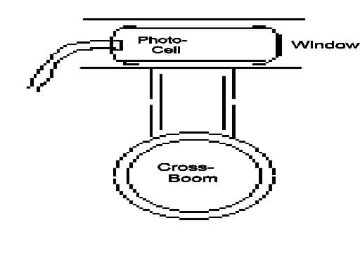
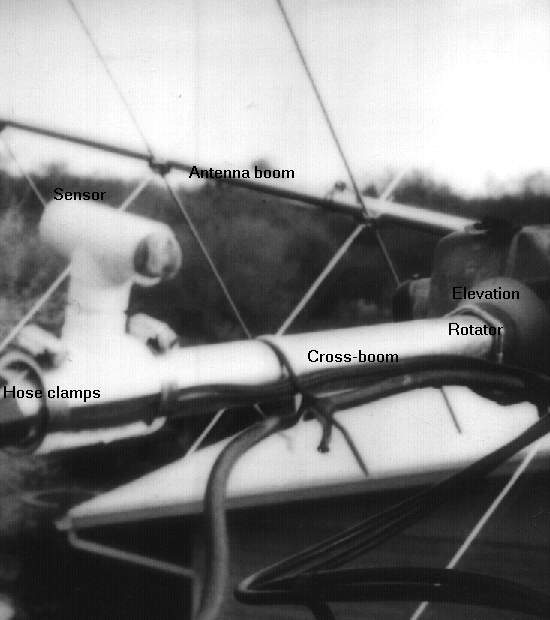
I took a 2-inch piece of plastic water pipe (e.g. 1 or 3/4 inch diameter), with endcaps. I use a CdS photoresistor (Radio Shack sells a packet of 5 for $2.29: item 276-1657. Only one is needed). Carefully mount the photocell inside one of the end caps, looking into the pipe, with the two wires going through small holes drilled in the endcap to the outside. Drill a hole in the center of the other end cap, roughly the same diameter as the photocell. Cover the open hole with something transparent, like a piece cut from the bubble pack the photocells came in, glued to the outside of the cap. This is just to keep the rain out. Wire an rf bypass capacitor (e.g. 0.01 microF disc ceramic) across the two photocell wires, outside the pipe. You should now be holding a 2-inch piece of plastic pipe with caps on each end, with two wires coming out of one end and a small window at the other end. Use other plastic plumbing components (T-junctions, adapters etc.) to complete the construction, and finally use hose clamps to attach the assembly to the cross-boom of your antennas (or anywhere convenient on the antenna, but not close enough to detune any of the antenna elements.)
Be careful to align the plastic pipe to be parallel to the antenna boom, with (obviously) the window looking along the direction of radiation. Now connect some twinflex to the two wires from the photocell, which are protruding from the rear endcap. In the shack, connect a cheap ohm-meter to the other end of the twinflex, and you've got a complete sun sensor. I use a Radio Shack analog multimeter ($4 at a hamfest: $10(?) at RS) permanently connected to the twinflex as the sensor readout. If you point the antenna towards the sun, you will see the resistance of the photocell, measured by the multimeter, drop to a few hundred ohms. It's very easy to peak the antenna up on the sun this way, and then to compare your rotator readouts to the predictions of InstantTrack or your favorite sun tracking program. When you're sure everything is working, be careful to seal all the components against the weather. This is the only difficult part of the construction.
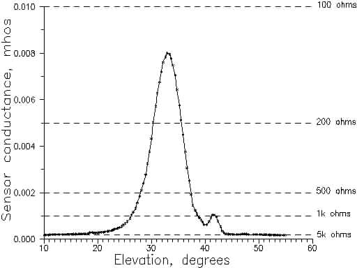
(1) When measuring the sun, the resistance of the photocell becomes a few hundred ohms. As the antenna slews towards the sun, the background sky brightness increases significantly. Even if you start a long way from the sun, it's easy to home in using the changes in background brightness detected by the photocell, even on a cloudy day. Because the sensor effectively averages the brightness over many square degrees, you can usually peak up quite accurately towards the sun. (Of course this doesn't work well if the clouds are clumpy.).
(2) In the light of the full moon, in a clear sky, the photocell resistance becomes a few hundred khoms to a Megohm. It's not sensitive enough to detect changes in background brightness as the sensor approaches the moon. You have to get quite close to the correct settings before you can detect the moon at all. Although it's easy to detect the full moon, I've not managed to detect a half-moon. Something more sensitive than a simple RS multimeter might help here if that were important.
(3) The hole in the front endcap should be roughly the same diameter as the photocell. This allows the maximum sensitivity. If it's much bigger, or much smaller, the response becomes flat-topped and it's a little more difficult to peak up exactly on the sun or moon.
(4) The beamwidth of the sensor (between half-sensitivity points) is roughly arctan(d/L) where d is the diameter of the photocell and of the front window, and L is the length of the tube (in the same units, of course). For example, with a window 8 mm in diameter and a tube 60 mm (about 2.4 inches) long, the beamwidth will be about 8 degrees. Since it's then easy to peak the antenna to the center of the response, to better than 1 degree, this is probably a convenient beamwidth. (You'd be surprised how difficult it is to find the full moon if you make a sensor with a 3 dB beamwidth of only 2 degrees.) If you want to have a narrower or wider response, use a longer or shorter tube.
(5) It is fairly critical to make sure the photocell is centered in the rear endcap, and that the window is centered in the front endcap. e.g. if one of these is "x" mm off-center, then the optical axis of the sensor will be roughly arctan(x/L) different from the mechanical axis of the pipe. A 1-mm error in positioning the window or the photocell will cause about a 1-degree squint with a 60-mm tube.
(6) I found that internal reflections from the sun, off the inside of the 2-inch tube, could cause confusing sidelobes when I was trying to home in on the sun. I ended up putting a tube of rolled-up, roughened black paper inside the pipe to minimize these internal reflections.
(7) I regularly check the alignment of my antennas, especially before events like a ZRO or EME test. I've often found that the antenna pointing has slipped by a few degrees, and that the rotator and mast-mounting hardware need tightening up. If I had a better mechanical mount for the antennas it probably wouldn't be so important. If the antenna alignment is not too far out, I do not try to realign the system mechanically. I measure how far the sun is from the calculated position, and then apply that as a correction offset when I point the antennas towards the satellite. It would be very convenient if software drivers used to control antenna rotators automatically allowed this zero-point error to be set as a parameter. Several commercial trackers do offer this feature.
(8) The most difficult part of the whole exercise is keeping the inside of the sensor, and the electrical connections, dry. Use all the usual techniques - silicon sealant etc. - that would be used on normal antenna connections.