MMA Project Book, Chapter 5 Section 3
MMA RECEIVERS: SIS mixers
Tony Kerr
S.-K. Pan
John Webber
Last revised September 21, 1998
Revision History:
9/21/98:
Added chapter number to section numbers. Placed
specifications in table format. Added milestone summary.
Summary
This section describes the SIS mixers to be used in MMA receivers.
They are expected to be used for all frequencies above 116 GHz. It is undecided
whether SIS receivers will be used below this frequency (perhaps down to
90 GHz), or whether HFET amplifiers will be preferable for their greater
immunity to interference and possible lower cryogenics cost. The goals
for the design and development phase are to produce working prototypes
of balanced, sideband-separating mixers with internal IF amplifiers meeting
the general specifications.
Table 5.3.1 SIS mixer specifications
|
Item
|
Specification
|
| Receiver noise temperature |
Single sideband noise as low as possible (4
to 8 photons equivalent, depending on band) |
| Frequency bands covered |
All atmospheric windows from ~90 to 1000 GHz;
230 GHz and 650 GHz bands during D&D phase |
| IF bandwidth |
Goal: 16 GHz total, both polarizations included;
want 8 GHz per sideband if possible |
| Configuration |
No mechanical tuners |
Table 5.3.2 SIS mixer milestones
| Preliminary Design Review |
1/29/99 |
| Critical Design Review |
9/30/99 |
| Deliver prototype for 230 GHz band (200-300
or 170-245) |
1/31/00 |
| Deliver prototype 602-720 GHz |
9/29/00 |
| Deliver test antenna 230 GHz mixers |
6/30/99 |
| Deliver test antenna 86 GHz mixers |
6/30/99 |
5.3.1 Performance
Figure 5.3.1 shows the DSB noise temperatures of SIS receivers reported
in the last few years. The best fixed-tuned receivers have DSB noise temperatures
in the range 2-4 hf/k up to ~700 GHz. Above ~700 GHz, receiver noise temperatures
rise rapidly because of RF loss in the Nb conductors. Work on new materials
is likely to improve high frequency results in the next few years (e.g.,
NbTiN for 700-1200 GHz).
Note that in calculating SSB system noise temperatures from DSB receiver
noise temperatures, care must be taken to include the appropriate image
input noise. The appropriate value of SSB receiver noise temperature is
given by:
TRSSB = 2TRDSB + Timage
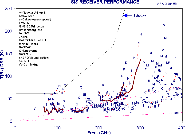
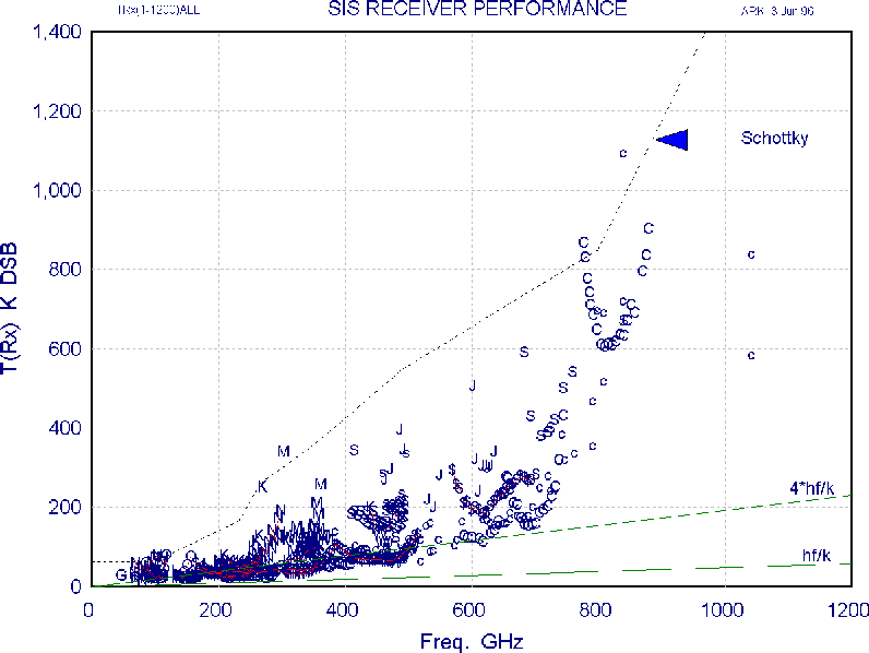
Figure 5.3.1 Reported SIS mixer receiver temperatures
Most of these receivers use a ~1.5 GHz IF, an exception being the SAO receivers
which use 4-6 GHz. The IF for the MMA is tentatively chosen as 4- 12 GHz
to give the desired 8 GHz IF bandwidth. The final choice of IF will depend
largely on the results of work now under way to develop an internal IF
stage for SIS mixers which will allow isolators to be eliminated from the
IF system. The best (individual) tunerless SIS receivers reported to date
in the 150-400 GHz range have frequency ranges 1.37:1, 1.42:1, and 1.54:1.
Their noise temperatures degrade quite precipitously beyond the band edges.
In making the 80 receivers required for each band on the MMA, we cannot
expect to achieve identical Tr vs. freq. characteristics, and the maximum
bandwidth common to all 80 receivers will be somewhat less than that of
the individual receivers. (Nb process control is something we are starting
to work on with our SIS fabricators, but hitherto there has been little
consideration given to such matters in SIS mixer production). It is hoped
that by the time we start building the MMA receivers we will be able to
achieve a 1.5:1 common bandwidth, but until this is actually demonstrated
we should be conservative to ensure we do not end up with unexpected gaps
in the frequency coverage.
5.3.2 Development
5.3.2.1 Capacitively coupled coplanar waveguide
To achieve wide RF bands (an upper to lower frequency ratio of 1.3
or greater) without mechanical tuning, a fully integrated (MMIC) mixer
design is required. The resulting "drop in'' mixer chips are relatively
easy to mount in blocks in which they are coupled to RF and LO waveguides.
Conventional microstrip MMIC technology is difficult to use above ~100
GHz because of the very thin substrates necessary to prevent coupling to
unwanted substrate modes. The use of coplanar waveguide (CPW) circuits
allows a thick substrate, but is prone to odd-mode resonances excited by
bends or near-by obstacles, and has poor isolation between adjacent lines.
CPW also requires inconveniently narrow gaps when a substrate of low dielectric
constant is used. To overcome these difficulties, we have developed capacitively
loaded coplanar waveguide (CLCPW), a CPW with periodic capacitive bridges.
The bridges are grounded at the ends, thus suppressing the odd mode, but
they also add a substantial capacitance per unit length to the CPW, which
allows desirable characteristic impedance levels to be obtained with convenient
dimensions. Figure 5.3.2 shows a 200-300 GHz quadrature hybrid composed
of CLCPW with periodic capacitive bridges.
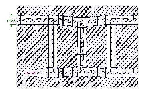
Figure 5.3.2. A 200-300 GHz quadrature hybrid using capacitively
loaded coplanar waveguide (CLCPW).
The bridges are 4 microns wide, and are connected to the ground plane at
their ends. The fourth port (lower left) has a built-in matched termination.
The substrate is 0.0035" fused quartz.
5.3.2.2 Sideband separating mixer
Even at the proposed site in Chile with its low atmospheric water vapor,
atmospheric noise in the image band of an SIS receiver will add substantially
to the system noise. The advantages of sideband separating mixers with
their image terminated in a 4 K cold load have been discussed (see MMA
Memos 168 and 170), and we expect to use sideband separating mixers in
at least the lower frequency SIS receivers. A developmental MMIC 230 GHz
sideband separating mixer is shown in Figure 5.3.3. The IF outputs from
the mixer are combined in an external quadrature hybrid which phases the
down-converted signals from the upper and lower sidebands so they appear
separately at the output ports of the hybrid. A useful property of the
sideband separating SIS mixer is that the sidebands can be swapped between
the two outputs simply by reversing the polarity of the bias on one of
the component mixers.

Figure 5.3.3(a). Block diagram of an SIS sideband separating mixer.
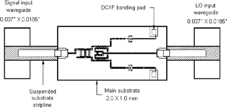
Figure 5.3.3(b). 230-GHz sideband separating mixer, showing the signal
and LO waveguides, suspended stripline coupling probes, and the main substrate.
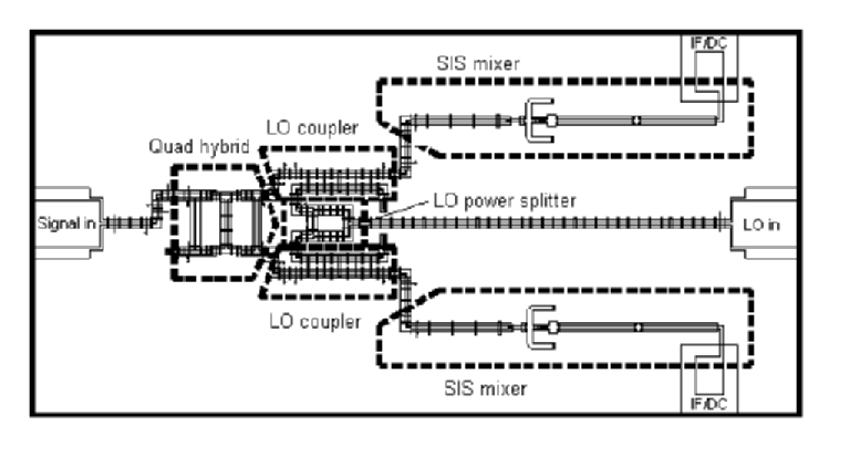
Figure 5.3.3(c). Substrate of the 230-GHz sideband separating mixer,
showing the main components.
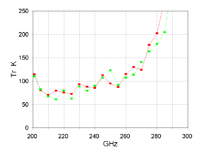
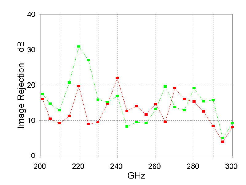
Figure 5.3.3(d) Receiver temperature and sideband separation for the
experimental mixer.
5.3.2.3 Balanced mixer
The use of balanced SIS mixers has two potential advantages for the MMA.
Compared with the usual ~20 dB LO coupler or beam splitter in front of
the mixer, a balanced mixer requires ~17 dB less LO power. This greatly
eases the task of developing wideband tunerless LOs. The other benefit
of a balanced mixer is its inherent rejection of AM sideband noise accompanying
the LO. A MMIC balanced mixer design is shown in Figure 5.3.4.

Click to zoom
Figure 5.3.4(a). Block diagram of a balanced SIS mixer.
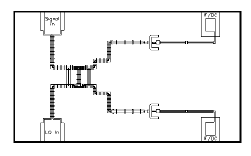
Figure 5.3.4(b). Substrate of a 230 GHz balanced mixer, showing the
quadrature hybrid and two SIS mixers.
5.3.2.4 Sideband-separating, balanced mixers
When the designs of the sideband-separating and balanced mixers have been
thoroughly tested, we will design and build a mixer which incorporates
both these features: a balanced, sideband-separating mixer. This will incorporate
the circuit elements whose design has already been proven individually.
This will produce for the MMA a mixer which requires a minimum of LO power,
provides good immunity to LO noise, and substantially reduces the contribution
to system noise of atmospheric noise in the unwanted sideband. The schematic
is shown in Figure 5.3.5. We expect that the mixer chip will be about 2
X 2 mm in size for 200-300 GHz.

Figure 5.3.5. Block diagram of a balanced, sideband-separating SIS
mixer.
5.3.2.5 Internal IF amplifier
Two options are being considered for the 8-GHz-wide IF in the SIS receivers
for the MMA. The conventional approach uses an IF isolator between the
mixer and IF amplifier, while a new scheme, developed at OVRO, uses an
IF amplifier stage inside the SIS mixer block and no isolator. The latter
scheme allows an IF covering more than an octave, tentatively 4-12 GHz.
The need for an isolator in the conventional scheme forces the IF center
frequency to at least 12 GHz (IF = 8-16 GHz) to achieve an 8 GHz bandwidth,
probably with a significant noise penalty. The penalty is not simply a
result of the increase in amplifier noise temperature at the higher frequency,
but includes the noise from the cold termination of the isolator which
is reflected from the mixer output.
The use of a high IF, as required by both the above schemes, imposes a
constraint on the output capacitance of the SIS mixer. In most SIS mixers,
the RF tuning circuit adds substantial IF capacitance in parallel with
the SIS junction. We have developed an SIS mixer with low IF capacitance,
and this design was used as a building block in the sideband separating
and balanced mixers described above.
In collaboration with S. Weinreb at the University of Massachusetts, we
have begun the design of an integrated IF amplifier which will permit the
MMA goal of 8 GHz instantaneous bandwidth per sideband to be realized.
The MMIC amplifier chip employs a grounded gate first stage and is expected
to give good performance over the 4-12 GHz target band.
5.3.2.6 Further plans
It is planned to continue the development of the 200-300 GHz sideband-
separating, balanced SIS mixer with integrated IF amplifier until the goals
of 5.3.1 are met. Once a number of these mixers have been evaluated,
the frequency bands for the MMA will be frozen and new designs will be
developed to cover those bands.
For the test receivers to be used for antenna evaluation, which mixers
are used will depend on the progress in development at the time they are
needed. The use of a standard DSB mixer with a 1-2 GHz IF range will
be sufficient for antenna tests, and such mixers may be used.
Back to Chapter 5 TOC
| Back to Chapter 5 Section 2
| On to Chapter 5 Section
4


