1998-11-12: Principal Milestones added, minor updates
Summary
In this section, hardware solutions to the problem of calibrating the MMA amplitude and phase are
described. Both solutions use the blocked area in the center of the subreflector as the source of
radiation from either a two-temperature load or a coherent signal source. A simple mirror
mechanism is used to select between the two systems. The coherent source may be made phase
stable through a round-trip measurement scheme so raising the possibility of continuous phase
measurement and correction as well as providing a valuable trouble shooting tool.
Table 3.2.1 Principal Milestones in Hardware Calibration Schemes
Task |
Completion
Date |
| 1) |
Demonstration of two temperature load. Hat Creek. |
1999-October |
| 2) |
Demonstration of coherent calibration signal with round trip phase
measurement. |
1999-March |
3.2.1 Introduction
The previous section describes a number of schemes for calibrating the MMA amplitude and phase.
This section outlines two specific hardware calibration schemes which can help to calibrate the
instrumental phase and amplitude of the MMA. Other instrumental calibration schemes, such as
round-trip phase calibration for the local oscillator, and AGC/total power monitors in the I.F. chain,
are described elsewhere.
The two calibration schemes outlined here are:
Absolute temperature sensitivity calibration, single dish mode
Relative amplitude and phase calibration, with an artificial coherent calibration signal
suitable for interferometric calibration
3.2.2 Absolute Temperature Calibration
This technique is only relevant to single dish total-power observations; it has been suggested by Jack
Welch and others, and is currently (July 1998) the subject of a joint MDC development between
BIMA and NRAO. It gives an absolutely calibrated signal of a few K at the receiver, over the
complete frequency range covered by the MMA. It has been described in
MMA Memo 225 by
Bock, Welch, Flemming and Thornton.
The essence of this technique is that a black body radiator is placed at the center of the subreflector
of each antenna, within the unused area of subreflector matching the central blockage of the antenna.
In this way there is no effect on antenna sensitivity.
Within this central part of the subreflector, a plane mirror switches between two (or more) hot loads
of different temperatures. The two loads have very precisely controlled and calibrated temperatures.
The total power output of the receiver is sampled synchronously with the mirror switching between
the two calibrated loads.
The added switched receiver noise is, to a first approximation, equal to the difference in temperature
of the two hot loads, multiplied by the beam solid angle of the absorbers at the subreflector seen
from the receiver feed, divided by the beam solid angle of the subreflector - assuming the receiver
feed itself is matched to the angle subtended by the receiver. This ratio will be reasonably constant
with frequency, but at a given frequency can be calibrated precisely by measurements of the feed
antenna pattern.
For more details see the memo by Bock, Welch, Flemming and Thornton. The joint development
with BIMA will show, on a timescale of a few months, how well the technique can be expected to
work in practice.
3.2.3 Interferometric relative phase and amplitude calibration
In the debugging stage of the MMA, there will be a need for a generic test signal that can be used to
debug the entire electronic system of a given antenna or antenna pair, from front-end to correlator.
When the antenna surface and pointing are sufficiently reliable, astronomical sources can be used for
this purpose, but having an independent, artificially generated signal that is not dependent on antenna
performance will be invaluable in checking out and maintaining the system.
If the calibration signal can be made coherent at all individual antennas, it opens up the possibility of
calibrating the entire receiver system, front-ends, back-ends and correlator, amplitude and phase as a
function of frequency, in a way independent of antenna tracking, pointing, or efficiency performance.
The calibration system should be sufficiently stable that it can be used as a secondary calibration
system, with only occasional cross-calibration with astronomical sources.
3.2.4 The Photonic Calibration System
The photonic calibration system has a broad-band, radiating antenna situated at the center of the
subreflector, where no extra antenna blockage is introduced. At the feed of the broadband antenna,
there is an uncooled photomixer device. A single optical fiber, carrying laser signals generated at a
central laboratory or control room, feeds this photomixer. In the simplest form, the optical signal
would come from two lasers, whose difference frequency corresponds to the telescope observing
frequency, and which is phase-locked to the telescope frequency standard. The equipment required
to do this would be nearly identical to that being developed for the photonic laser local oscillator
system. Only one pair of lasers would be required for the entire array; the combined laser output
would be split optically N ways (where N is the number of antennas) and routed via N independent
fibers to each antenna.
In slight variants of this scheme, either a single laser signal, or the dual laser system tuned to the
required mm-wave difference frequency, could be modulated. The modulation might take the form
of a regular comb spectrum, simulating broadband noise. This becomes quite analogous to the pulse
cal system developed for the VLBA, and could be used for checking the relative amplitude and
phase response over the entire interferometric IF passband. The modulation might also be a truly
random, or a pseudo-random digitally generated sequence, which would also provide a broad-band
coherent test signal. This random or pseudo-random noise needs to be coherent at each antenna, so
timing considerations, within a fraction of the reciprocal bandwidth, are important.
Naturally this injected signal needs to be stable, both in amplitude and phase. It may require
round-trip delay compensation of some type, and perhaps an AGC system to keep the signal
amplitude constant. However, attention to the stability of this calibration signal may relax the
technical requirements elsewhere in the system.
Most of the development for this coherent photonic calibration scheme is already being undertaken in
the context of the photonic local oscillator development. The calibration scheme should in principle
be much simpler, because several orders of magnitude lower radiated mm-wave power is required.
The main additional development needed is that of the broad-band radiating antenna, to be sited at
the subreflector, fed by the signal from the photomixer. The broadband antenna is the subject of a
joint NRAO-MDC (OVRO) development project.
3.2.5 Combined Calibration System
The incoherent calibration scheme described earlier switches between blackbody radiators of
different temperatures using a mirror. In principle, by allowing an extra position on this mirror, the
radiated calibration signal can be switched between the incoherent blackbody loads and the coherent
radiator. At a later stage in the development, when the feasibility of both coherent and incoherent
calibration schemes has been demonstrated, the combination of the different calibration radiators into
one package will receive attention, as will studies of how to achieve the necessary amplitude and
phase stability.
3.2.6 Work to be done
Much of the work is being carried out at BIMA (incoherent calibrator) and OVRO (coherent
calibrator). The photonic calibration builds on work already in progress in the context of the
photonic local oscillator scheme, with the exception of the broadband antenna. Some simple design
work is required now (e.g. exactly how much coherent power needs to be radiated from the
subreflector, with what requirements on amplitude and phase stability?) but the bulk of the effort can
be expected fairly late in the MMA development phase.
Reference:
D. Bock, J. Welch, M. Flemming and D. Thornton,
MMA Memo 225: "Radiometer Calibration at
the Cassegrain Secondary Mirror." (See also the Appendix below.)
APPENDIX
The following figures are from the
MMA Memo 225 by Bock, Welch, Fleming and Thornton,
"Radiometer Calibration at the Cassegrain Secondary Mirror."
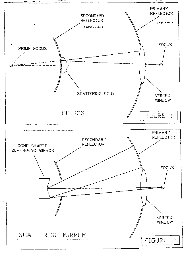
Figure 1 shows the general Cassegrain optics, which normally has a scattering cone covering the
central part of the subreflector to direct unwanted rays on to cold sky. Figure 2 shows a scattering
mirror behind the subreflector, giving much the same effect.

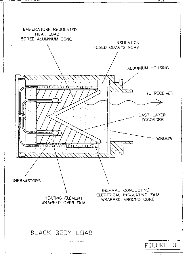
Figure 3 shows the absorbing black body load that would be placed behind the central hole of the
subreflector

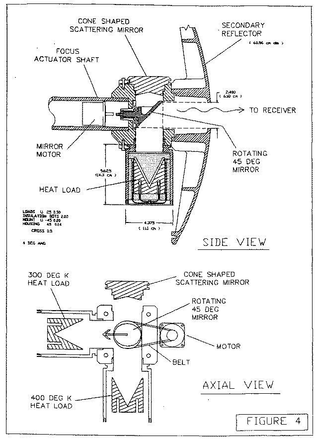
Figure 4 shows the arrangement of a rotating 45-degree mirror which will choose between one of
two hot loads, whose temperatures differ by ~100 K, and the scattering cone from which rays which
eventually reach cold sky.


