(This is a summary. Last modified May 25 1997)
The full article appeared in QST, Vol 81, No.6,
 June 1997,pp.43-44, published by the ARRL.
The Twelfth-Wave Transformer is often a more convenient alternative to the more well-known quarter-wave transformer. It is not a new concept, being first publilshed in 1961, but it is relatively unknown in amateur radio circles.
With the quarter-wave transformer, two impedances Z1 and Z2 are matched by using a quarter-wave of transmission line of characteristic impedance sqrt(Z1.Z2). This works well, but often requires a non-standard characteristic impedance. For example, to match a 50-ohm load to 75-ohm cable, a quarter-wave transformer needs a length of cable of characteristic impedance 61.2 ohms.
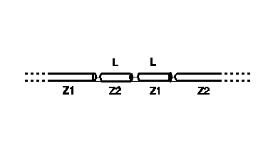
With the twelfth-wave transformer, two lengths of cable are used in series, each electrically nearly one twelfth-wavelength, but of characteristic impedances equal to the two impedances Z1 and Z2 being matched. The figures below illustrate the difference between the twelfth-wave and a quarter-wave transformer.

The above figure illustrates the Twelfth-Wave transformer. To match impedances Z1 and Z2, two lengths of cable are needed, each of length L close to one electrical twelfth-wavelength. The characteristic impedance of one length is Z1, of the other Z2.
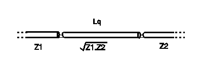
As illustrated above, with the quarter-wave transformer, only one matching cable is required, of electrical length Lq=one quarter wavelength, but this is very often a non-standard characteristic impedance.
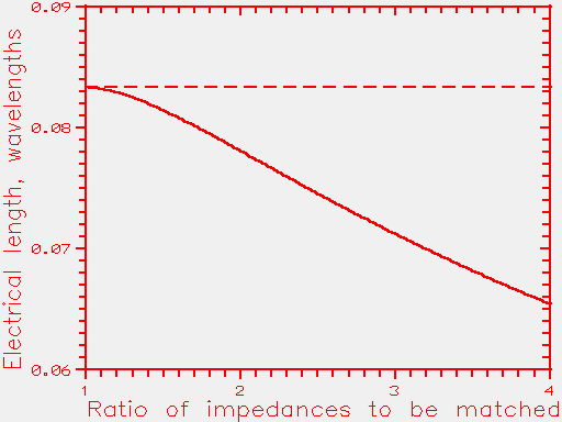
The precise electrical lengths needed in the twelfth-wave transformer are just slightly less than an exact twelfth. When matching impedances Z1 and Z2, if B=Z1/Z2, then the precise electrical length of the "twelfth"-wave section is given by:
L = [arctan(sqrt(B/(B^2 + B +1)))]/(2.pi)
where the arctan function is assumed to return an angle in radians. L is the electrical length of each section of matching cable, measured in wavelengths.
The length L is plotted below as a function of the impedance matching ratio, Z1/Z2. The horizontal dashed line corresponds to an exact twelfth length (0.0833333).
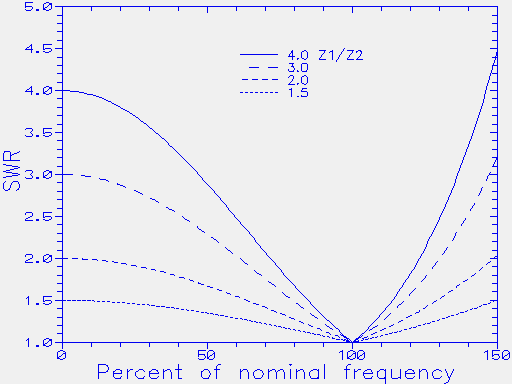
The SWR bandwidth of the twelfth-wave transformer is very broad, and is comparable to the quarter-wave transformer. The plot below shows the resulting SWR as a function of frequency, where a twelfth-wave transformer is used to match impedance ratios Z1/Z2 of 1.5, 2, 3 and 4. The frequency axis extends from D.C. to 50% higher than the nominal design frequency.
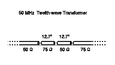
A transformer for 50 MHz, matching 75 to 50 ohms: From the figure, or the equation, the required length of matching section is 0.0815 wavelengths. At 50 MHz (=6-meter wavelength) this becomes 0.489 meters. Allowing for a velocity factor of 0.66, the physical length bcomes 0.323 meters, or 12.7 inches. The figure below illustrates the complete transformer.
Suppose we wish to match two elements of a phased array, individually fed by a matched 50-ohm cable. Putting the two feeders to the individual elements in parallel gives a combined impedance of 25 ohms. To match this 25-ohm impedance to conventional 50-ohm cable, we need a length of 50-ohm, and a length of 25-ohm cable. The 25-ohm length can be constructed by putting two 50-ohm lengths in parallel. The figure below shows the general arrangement.
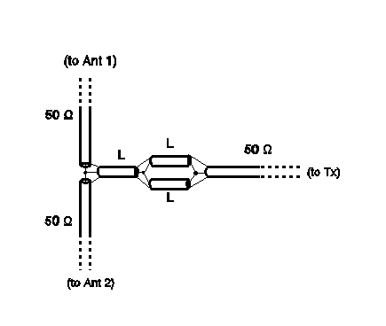
In the above figure, since we are matching an impedance ratio of 2:1, each length L is (from the above equation or the figure given the required length of matching section for a given transformation ratio) 0.0781 wavelengths. If this were to be used at 28 MHz (10.7 meters) the length becomes 0.836 meters. Allowing for a velocity factor of 0.66, this becomes a physical length of 0.552 meters or 21.7 inches. All lengths L would be 21.7 inches, and all cables are of the same (e.g. 50 ohm) characteristic impedance..
Note that this is a perfectly general way of solving the matching problem of putting N feeders, each of impedance Z0, in parallel. The required matching section impedances are Z0, and Z0/N. It is always possible to make a feeder of characteristic impedance Z0/N simply by putting N sections of impedance Z0 in parallel.
Although relatively unknown in amateur radio circles, the twelfth-wave transformer was first described in 1961, when it was in use for matching 200 MHz components at the CERN accelerator. See:
"A Convenient Transformer for Matching Coaxial Lines"
by B. Bramham, in Electronic Engineering, Vol 33, pp.42-44,
January 1961.
Since the appearance of the article in the June 1997 QST, I have received some correspondence from QST readers asking for further clarification on the use of the Twelfth-Wave Transformer. In the hope that it may help others, replies given to readers can be found on this link.