(Feb 1, 2008) There has been some confusion regarding how to convert the autocorrelation functions (ACFs) recorded by the WAPPs into spectra. This is basically just a FFT, but has a few complications: The source of the problem is that there are several different ways to do the FFT (including whether or not to pad the ACF with zeros), and each ends up with a slightly different set of channel frequencies, shifted from each other by half a channel. This whole discussion applies to the Spigot as well, but I haven't tested any Spigot data.
In the following, we'll say that the WAPPs have recorded N lags. Since the ACF is symmetric, only the zero-lag and N-1 positive-lags are saved. N is typically even (but not necessarily a power of two) in WAPP data. Data is taken at a center frequency of F and bandwidth B. All arrays are zero-indexed.
The first FFT method is the one currently used by Sigproc and Presto1 to convert WAPP data: An array of size 2N is created. This is filled with the N original ACF values and the N-1 mirrored nonzero lags, explicitly creating a symmetric ACF. The remaining array element is set to 0, to keep the total length even. This array is then input to a real-to-complex (R2C) FFT. This results in N+1 output channels2, so the center frequency F comes out in the middle of channel N/2. The imaginary component of the output is expected to be zero due to the symmetry so those values are ignored.
The half-channel error arises since the current codes treat the output of this FFT as only having N channels, and thus put F between channels N/2-1 and N/2.
Another way to think of this is to calculate the frequency that corresponds to DC at the sampler: FDC=F-B/2. When doing a standard FFT such as the R2C, this frequency will always come out in the center of channel 0, independent of the number of lags and whether any zero-padding was done. The channel spacing is 2B/Nfft, where Nfft is the number of points input to the FFT (Nfft=2N in the usual case).
For the R2C method, the correct center frequencies for each channel should be computed as follows:
This formula applies for both inverted and non-inverted bands, using the convention of setting B<0 for an inverted band.
Another transform that can be used to do the conversion is one of the discrete cosine variants, the DCT-III (aka FFTW_REDFT01). This has several benefits: The N lags can be input directly without mirroring or padding, resulting in cleaner and sometimes faster code (see below for a discussion of processing speed). In the DCT-III, the output is implicitly shifted by half a channel, resulting in N channels with F between channels N/2-1 and N/2. With this method the edge channels are in principle usable (although in reality probably still marginal due to the analog filter rolloff).
The correct channel center frequencies for this method (with the same treatment of inverted bands) are:
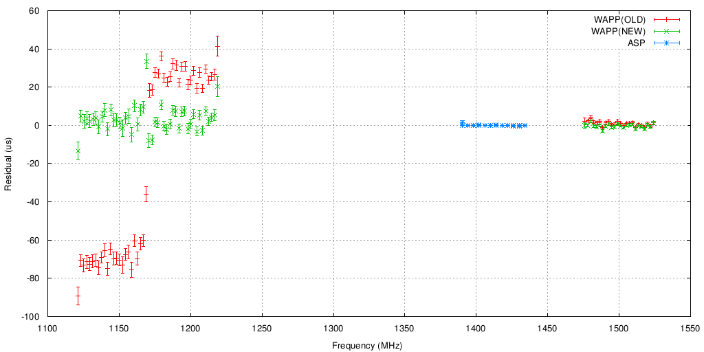
Below are some comparisons of 1937+21 timing using these different methods on WAPP data. ASP data is shown for comparison, and was used to fit for the current DM at this epoch. No fitting was done on the WAPP TOAs. After the lag-to-spectrum conversion and dedispersion, the WAPP profiles were summed in blocks of 8 channels to make the trend vs. frequency more obvious.
WAPP(OLD) is the current R2C FFT and channel labelling scheme
used by Sigproc and Presto. WAPP(NEW) is the same FFT scheme but
new/correct frequency labeling. The half-channel error for WAPP1
happens in the opposite direction (relative to sky frequency) since
its band was inverted in this observation.
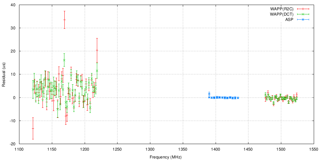
WAPP(R2C) is the old FFT scheme, WAPP(DCT) is the new DCT-III
scheme. In each case the appropriate channel frequencies were used.
The DCT method seems to have improved the band edge TOAs, otherwise
the two look pretty similar.
Scott did some benchmarking of the different FFT methods, using FFTW's bench program (FFTW 3.1.2, gcc 3.4, 2.6 GHz Intel Core2 Duo):
Real-to-complex FFT of twice the length:
./bench -s irf512 irf1024 irf2048 irf4096
Problem: irf512,   setup:  28.56 ms, time:  1.98 us, ``mflops'': 5805.4
Problem: irf1024,  setup:  48.47 ms, time:  4.02 us, ``mflops'': 6375.1
Problem: irf2048,  setup:  85.73 ms, time:  8.41 us, ``mflops'': 6699.8
Problem: irf4096,  setup: 145.86 ms, time: 18.81 us, ``mflops'': 6531.8

DCT-I:
./bench -s k257e00 k513e00 k1025e00 k2049e00
Problem: k257e00,  setup:  26.31 ms, time:  3.34 us, ``mflops'': 1538.3
Problem: k513e00,  setup:  39.50 ms, time:  6.47 us, ``mflops'': 1784.9
Problem: k1025e00, setup:  66.27 ms, time: 10.88 us, ``mflops'': 2356.7
Problem: k2049e00, setup: 119.42 ms, time: 26.12 us, ``mflops'': 2157.0

DCT-III:
./bench -s k256e01 k512e01 k1024e01 k2048e01
Problem: k256e01,  setup:  8.23 ms, time:  2.14 us, ``mflops'': 2391.8
Problem: k512e01,  setup: 14.54 ms, time:  4.55 us, ``mflops'': 2533.6
Problem: k1024e01, setup: 26.23 ms, time:  9.38 us, ``mflops'': 2730.7
Problem: k2048e01, setup: 40.60 ms, time: 21.06 us, ``mflops'': 2673.9
These results show that there isn't really much of an difference in speed when going from the R2C FFT to the DCT-III, and the DCT-I is about 30% slower. In older versions of FFTW, the DCT method was faster (which is why Presto uses it), so this situation may change in the future. The small (~10%) speed difference between the R2C FFT and the DCT-III is likely lost when the cost of creating the mirrored ACF is factored into the total R2C cost (it's not included in the numbers above).
1 Presto actually uses a padded DCT-I (FFTW_REDFT00), which is mathematically equivalent to the R2C but can be more efficient (depends on which FFTW version is in use).
2 The two edge channels each only have B/2N (i.e., half a channel's worth) of non-redundant BW, so the total bandwidth is still B. These edge channels also contain aliased copies of themselves, so they probably should not be used (but they're out on the filter edge anyways so it's not a big loss).