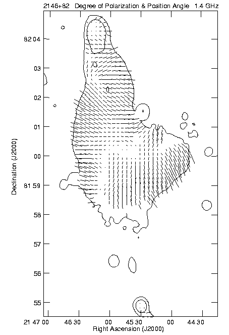
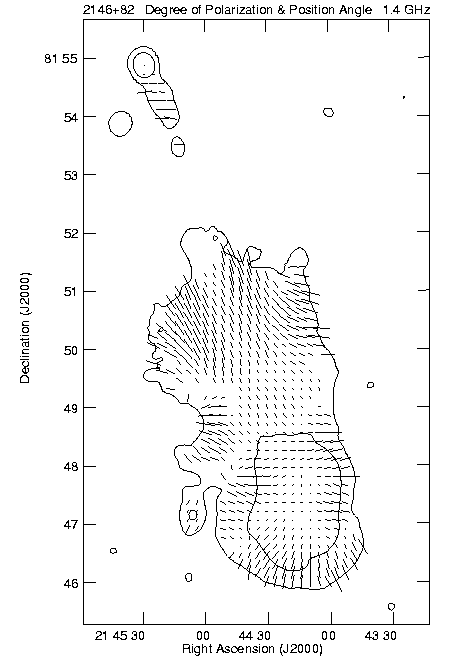
Figure 6: Distribution of degree of 1.4 GHz linear polarization p and E-vector
position angle over the north D (left) and south E (right)
lobes of the source at 13''
(FWHM) resolution, superposed on selected contours of total intensity.
A vector of length 15'' corresponds to p=0.5.
The polarization structure derived from the sensitive BnC configuration observations is shown in Figure 6. The 1.4 and 1.6 GHz data are sufficiently separated in frequency to enable us to measure Faraday rotation but still maintain comparable surface brightness sensitivity. The derived rotation measure images of the two lobes are shown in Figure 7. The rotation measure distribution over the north lobe is featureless but several filamentary rotation measure structures can be seen over the southern lobe. The average rotation measure is about the same in the two lobes, -9 rad m-2 in the north and -8 rad m-2 in the south. The Faraday rotation measure in the south lobe has a somewhat larger root mean square variation, 8 rad m-2 compared to 5 rad m-2 in the north.
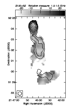
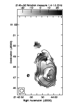
Figure 7: Gray scale representation of the rotation measure at 20''
resolution with superimposed contours of the 1.6 GHz total
intensity at the same resolution.
The bar at the top gives the grayscale values and the resolution
is shown in the lower-left corner.
The north lobe is shown in the left and the south lobe on the right.