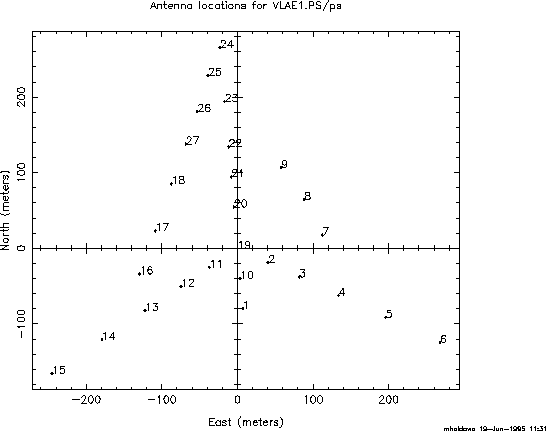
Figure 5.4: Example of a possible E configuration requiring only 9 new antenna stations and two new rail spurs.
Support of an ultra-compact E configuration requires construction of new antenna stations and rail access to them. Careful consideration must be given to the number of new stations needed and their placement.

Figure 5.4: Example of a possible E configuration requiring only 9 new
antenna stations and two new rail spurs.

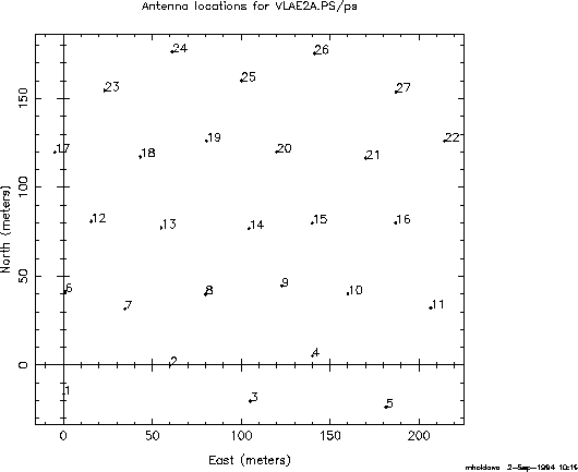
Figure 5.5: Example of a more optimum E configuration, requiring 27 new
stations and 5 or six new rail spurs.
One possibility (E1) is to move the outer three antennas from each of the three arms of the D configuration to the inner part of the configuration. This option would require only 9 new stations and two new rail spurs (Fig. 5.4). The E1 configuration would have a maximum baseline of 500 m. Simulations have shown that it would achieve a given surface brightness sensitivity in half the time as an optimally tapered observation with the D configuration.
A more optimal configuration (E2) would require essentially 27 new stations and 5 or 6 new rail spurs. It could be designed to provide essentially Nyquist-sampled u-v coverage and a small grating response. Simulations of one such configuration (Fig. 5.5) indicate that it could be 5-10 times faster than the D configuration in reaching a given surface brightness.
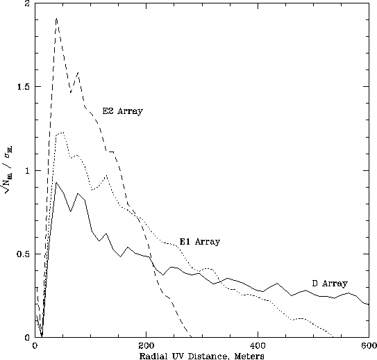
A comparison of the relative sensitivities of the D, E1, and E2 configurations (parameterized as the filling factor of antennas in the area covered by the array) is shown in Fig. 5.6. While the E2 configuration is preferable to the E1, preliminary cost estimates show that it comes at four times the cost of the E1. A detailed cost-benefit analysis is clearly needed.

Figure 5.6: Relative sensitivities of the D, E1 and E2 configurations.
Shadowing is of little concern for either of these possibilities.
Simulations have shown that there is little shadowing for hour angles
-3h<HA<+3h for source declinations  . Long
tracks will not be needed for good u-v coverage; snapshots at several
hour angles will suffice for many programs. For low declination
sources, a hybrid or ``E-south'' array configuration may be needed.
The E configuration will be, above all, a mosaicing configuration. Successful exploitation of the E configuration will require a total power capability on all antennas, as discussed in .2.4.