Next: 3.3 Parameter variations
Up: 3 The model
Previous: 3.1 Assumptions
3.2 Geometry
We define  to be the angle between the jet axis and the line of
sight.
to be the angle between the jet axis and the line of
sight.  is a coordinate along the jet axis with its origin at the
nucleus,
is a coordinate along the jet axis with its origin at the
nucleus,  is measured perpendicular to the axis,
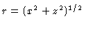 is the distance from the nucleus and
  is an angle measured
from the jet axis (
is an angle measured
from the jet axis ( ). The first step in our procedure is
to define functional forms for the outer surfaces of the jets and for the
flow streamlines. The latter inevitably involves some guesswork, to be
justified post hoc by the quality of the model fit. Inspection of the
outer isophotes shows that the jets can be divided into three regions:
). The first step in our procedure is
to define functional forms for the outer surfaces of the jets and for the
flow streamlines. The latter inevitably involves some guesswork, to be
justified post hoc by the quality of the model fit. Inspection of the
outer isophotes shows that the jets can be divided into three regions:
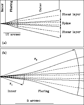
- Inner (0 - 2.5 arcsec): a cone, centred on the nucleus, with a
half-opening angle of 8.5 degrees.
- Flaring (2.5 - 8.3 arcsec): a region in which the jet initially
expands much more rapidly and then recollimates.
- Outer (8.3 - 28.3 arcsec): a second region of conical expansion,
also centred on the nucleus, but with a half-opening angle of 16.75 degrees.
All dimensions given above are as observed, i.e. projected on the plane of
the sky. This pattern of an initially narrow base and a rapid
expansion followed by recollimation is general in FRI jets (Bridle & Perley ,
).
In what follows, we use subscripts i, f and o to refer to quantities
associated with the inner, flaring and outer regions. We refer to the
inner and outer boundaries separating the regions by subscripts  and
and
 . The inner boundary is the flaring point defined by
Parma et al. (1987) and
Laing et al. (1999),
and we also use this term.
. The inner boundary is the flaring point defined by
Parma et al. (1987) and
Laing et al. (1999),
and we also use this term.
Guided by the shape of the outer isophotes, we assume that the flow in the
inner and outer regions is along straight lines passing through the
nucleus. Our general approach is to devise simple analytical functions to
describe the flow in these regions, and then to interpolate across the
more complex geometry of the flaring region in such a way as to preserve
continuity. Families of streamlines are parameterized by the streamline
index  , which varies from 0 at the inner edge of a component (spine or
shear layer) to 1 at the outside edge. In the inner and outer regions,
the streamlines make constant angles
, which varies from 0 at the inner edge of a component (spine or
shear layer) to 1 at the outside edge. In the inner and outer regions,
the streamlines make constant angles  and
and  with the jet axis. We define
  and
and  to be the
half-opening angles of the jet in the inner and outer regions, and
to be the
half-opening angles of the jet in the inner and outer regions, and
 ,
,  to be the corresponding angles for the
spine. s is defined in terms of these angles in Table 3.
to be the corresponding angles for the
spine. s is defined in terms of these angles in Table 3.
Table 3:
Definitions of streamline indices for inner and outer
regions.
| Model |
Inner (conical) |
Outer (conical) |
| SSL spine |
 |
 |
| SSL shear layer |
 |
 |
| Gaussian |
 |
 |
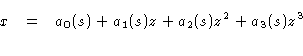
We require continuity of the streamlines and their first derivatives with
respect to across the flaring region. The simplest functional form
that satisfies these constraints and fits the outer isophote shape for  in the shear layer is:
For each streamline, the values of  -
-  are determined
uniquely and in analytic form by the continuity conditions. The natural
boundaries between regions are then spherical, centred on the nucleus
at distances
are determined
uniquely and in analytic form by the continuity conditions. The natural
boundaries between regions are then spherical, centred on the nucleus
at distances  and
and  and therefore perpendicular to the
streamlines. Fig. 4 shows sketches of the assumed
geometry for the SSL model (the equivalent for the Gaussian model is
essential identical, but with the spine removed).
and therefore perpendicular to the
streamlines. Fig. 4 shows sketches of the assumed
geometry for the SSL model (the equivalent for the Gaussian model is
essential identical, but with the spine removed).
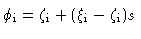
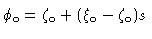
In order to describe variations along a streamline, we use a coordinate
 , defined as:
is monotonic along any streamline and varies smoothly from to
through the flaring region ( on the axis). This allows us
to match on to simple functional forms which depend only on
on the axis). This allows us
to match on to simple functional forms which depend only on  .
.
The functions defining the edge of the jet are constrained to match the
observed outer isophotes and are fixed in a coordinate system projected on
the sky. Their values in the jet coordinate system then depend only on
the angle to the line of sight. The outer edge of the spine in SSL models
is not constrained in this way, and the relevant parameters may be varied
in order to obtain a good fit to the data.
In what follows we will refer to streamline coordinates defined by
longitudinal (along a streamline), radial (outwards from the
axis) and toroidal orthonormal vectors.
Figure 4:
Geometry of the spine/shear-layer model, showing the inner,
flaring and outer regions in the plane containing the jet axis. The thick
full curves represent the edge of the jet, the boundaries between regions
are represented by thin full curves and the  streamlines for the
spine and shear layer are drawn as dashed curves. (a) The entire modelled
region; (b) the base of the jet on a larger scale, showing the boundary
surfaces at distances of and from the nucleus. The Gaussian
model is essentially the same, but with the spine component removed.
streamlines for the
spine and shear layer are drawn as dashed curves. (a) The entire modelled
region; (b) the base of the jet on a larger scale, showing the boundary
surfaces at distances of and from the nucleus. The Gaussian
model is essentially the same, but with the spine component removed.
 |